
Flapping rotor device with ascending shaft wing vertically operating and descending shaft wing horizontally operating

A flapping-rotor, horizontal technology, applied in the field of aircraft, can solve the problems of high cost, poor stability, difficult manufacturing and design, etc., and achieve the effects of reasonable design, convenient control and simple structure

Inactive Publication Date: 2021-03-05
GUANGDONG GUOSHIJIAN TECH DEV CO LTD
View PDF4 Cites 2 Cited by
  • Summary
  • Abstract
  • Description
  • Claims
  • Application Information

AI Technical Summary

Problems solved by technology

[0003] In recent years, although there have been some technologies that combine flapping wings and rotors, that is, by using the flexible deformation of the flapping wings, the upward lift and forward thrust are generated when the flapping wings flap, and the antisymmetrical thrust forms a force couple at the same time, driving The flapping wing performs self-driven rotation, and the circumferential motion speed generated by the rotation can increase the lift, so as to achieve the purpose of increasing the overall lift. However, it has been found through experiments that the current flapping rotor device cannot provide enough lift for the aircraft. The ratio to the weight of the structure is very low, and the ability to take off normally has not been achieved
It can be seen that the existing flapping rotor devices often have disadvantages such as complex structure, bulky body, poor stability, difficult manufacturing design and high cost. These technical defects greatly limit the rapid development of flapping rotor devices

Method used


Image

  • Flapping rotor device with ascending shaft wing vertically operating and descending shaft wing horizontally operating
  • Flapping rotor device with ascending shaft wing vertically operating and descending shaft wing horizontally operating
  • Flapping rotor device with ascending shaft wing vertically operating and descending shaft wing horizontally operating

Examples


Embodiment Construction

[0038] Embodiments of the present invention are described in detail below.

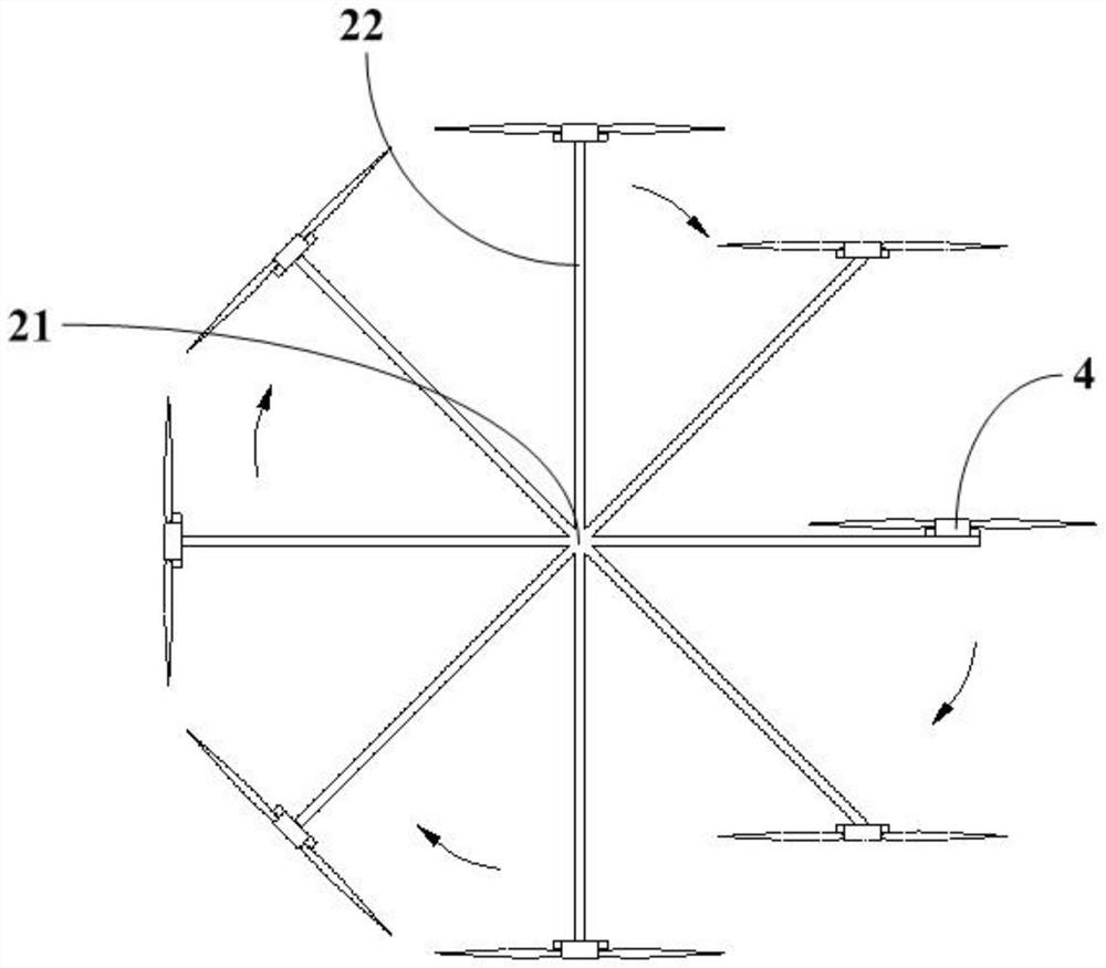
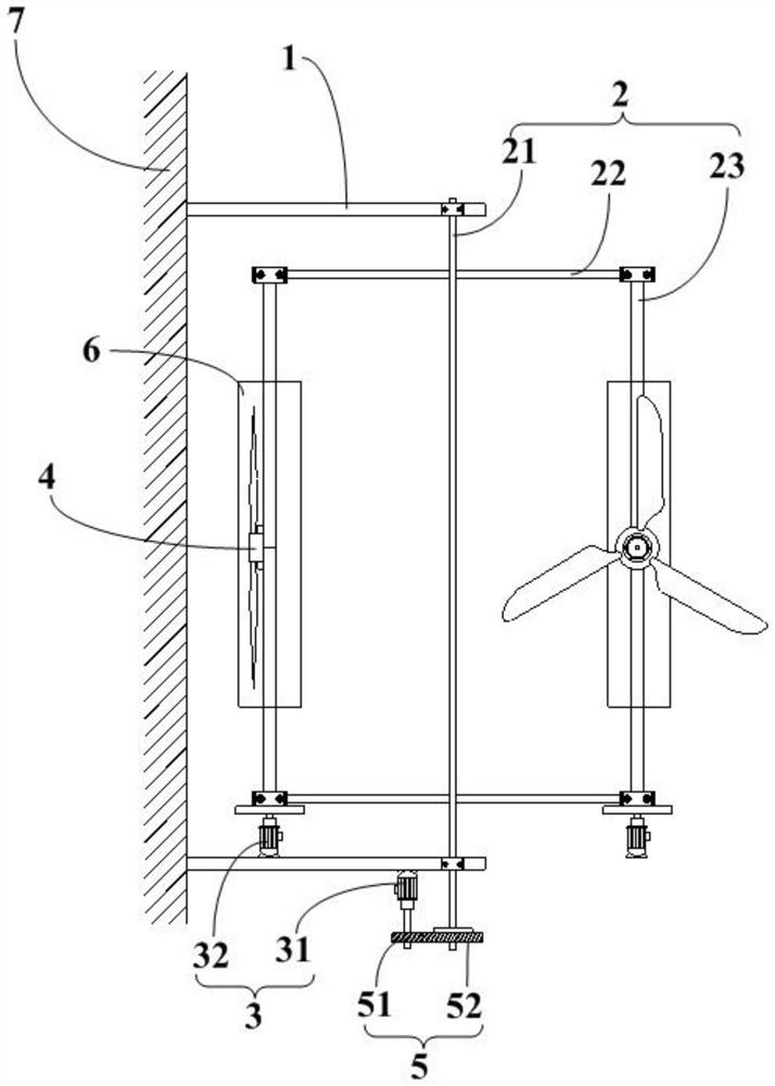
[0039] The invention discloses a flapping rotor device for vertical operation of upward shaft wings and downward horizontal operation, comprising:

[0040] Support assembly 1, the support assembly 1 is arranged on the side wall of the fuselage 7, and is fixedly connected with the fuselage 7;

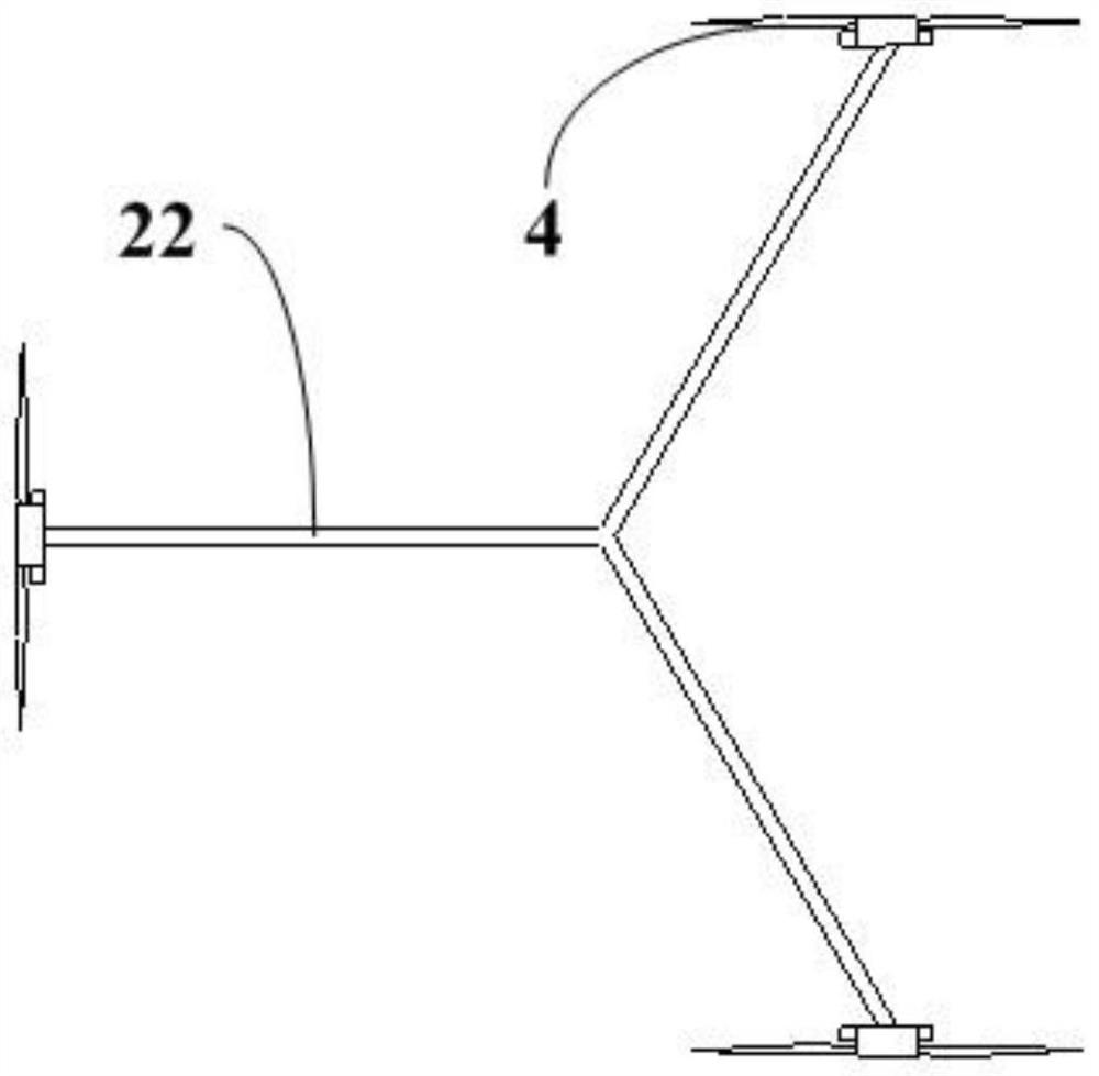
[0041] Rotation assembly 2, the rotation assembly 2 includes a revolution main shaft 21, a rotating arm 22 and an autorotation main shaft 23, the revolution main shaft 21 passes through the support assembly 1 and is rotatably connected with the support assembly 1; The rotation main shaft 23 passes through the other end of the rotating arm 22 and is perpendicular and rotatably connected to the rotating arm 22, and the revolution main shaft 21 and the axis of the rotation main shaft 23 are arranged in parallel;

[0042] Drive assembly 3, the drive assembly 3 includes a first drive motor 31 and a second drive moto...


PUM


Abstract

The invention discloses a flapping rotor device with an ascending shaft wing vertically operating and a descending shaft wing horizontally operating, which comprises a support assembly, a rotating assembly, a driving assembly, a rotor assembly and a transmission assembly, and is characterized in that the supporting assembly, the rotating assembly, the driving assembly, the rotor assembly and the transmission assembly are in linkage fit, an autorotation spindle in the flapping rotor device can revolve under the driving of a revolution spindle, and meanwhile, autorotation is kept under the driving of a second driving motor. According to the flapping rotor device, in the descending revolution process of the autorotation spindle, the rotation surface of the rotor assembly is always kept parallel to the horizontal plane under the driving of the second driving motor, so that vertically upward lifting force is continuously provided for an aircraft; and in the ascending revolution process of the autorotation spindle, the second driving motor drives the rotor assembly to keep the rotating surface of the rotor assembly perpendicular to the axis of the rotating arm all the time, so that resistance is not generated or small resistance is generated, counteracting of lift force in the revolution process of the rotor wing assembly is avoided, and continuous and stable lift force is provided for the aircraft.

Description

technical field [0001] The invention relates to the technical field of aircraft, and more particularly to a flapping rotor device with an upward axis running vertically and a downward running horizontally. Background technique [0002] The flapping-wing aircraft is a flying device designed to imitate the flapping motion of insects or birds. The flapping-wing aircraft mainly relies on the flapping of the blades to generate lift, which can provide greater lift for the aircraft. The flapping-wing aircraft has vertical take-off and landing, hovering, Compared with fixed-wing and rotary-wing aircraft, flapping-wing aircraft has many advantages such as simple structure, light weight, low cost and high efficiency. If the flapping flight technology and the rotor flight technology can be combined, it will not only have the advantages of vertical lift-off and aerial hovering of the rotorcraft and helicopter, but also realize that the aircraft consumes less energy during flight, is eas...

Claims


Application Information

Patent Timeline
IPC IPC(8): B64C27/22B64C27/32B64C33/02B64D27/24B64D35/02B64D35/00
CPCB64C27/22B64C27/32B64C33/02B64D27/24B64D35/02B64D35/00
Inventor 王志成
Owner GUANGDONG GUOSHIJIAN TECH DEV CO LTD
Learn More