
Vehicle-mounted movable multifunctional sludge treatment vehicle

A sludge treatment vehicle, multi-functional technology, applied in the direction of sludge treatment, water/sludge/sewage treatment, chemical instruments and methods, etc., can solve problems such as time-consuming and cost-consuming, long processing time, and danger, and achieve Reduce the number of people going down to the well to clean up, reduce the cost of cleaning and transportation, and facilitate the movement

Pending Publication Date: 2021-03-02
杭州诚臻工程机械有限公司
View PDF0 Cites 0 Cited by
  • Summary
  • Abstract
  • Description
  • Claims
  • Application Information

AI Technical Summary

Problems solved by technology

[0002] Sludge is a common kind of environmental pollution, especially after the rain, and after the construction work is completed, a large amount of sludge mixed with rainwater will be produced on the construction site or muddy ground. At present, the municipal industry uses a single-function pipeline dredging vehicle, Pipeline dredging, sewage suction trucks, manual cleaning, sludge removal vehicles, etc. to achieve pipeline dredging, sewage sludge dredging, and then transport the sludge and sewage to a fixed sludge treatment station for dehydration treatment. This treatment method requires a lot of Manual intervention, and the processing time is relatively long, which is extremely inconvenient, time-consuming and expensive, and dangers often occur during the artificial cleaning process

Method used


Image

  • Vehicle-mounted movable multifunctional sludge treatment vehicle
  • Vehicle-mounted movable multifunctional sludge treatment vehicle
  • Vehicle-mounted movable multifunctional sludge treatment vehicle

Examples


Embodiment Construction

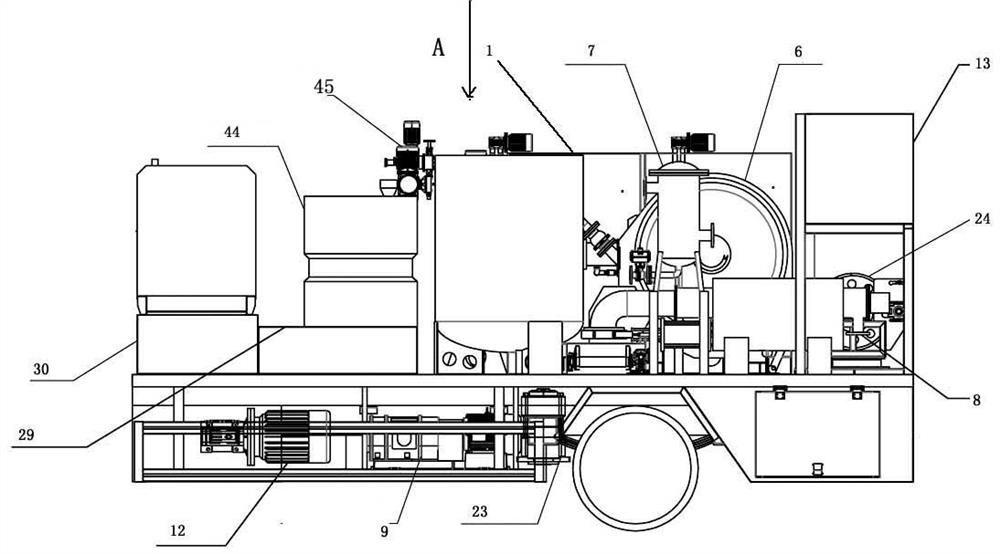
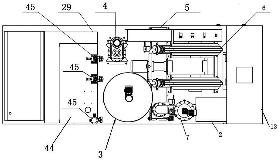
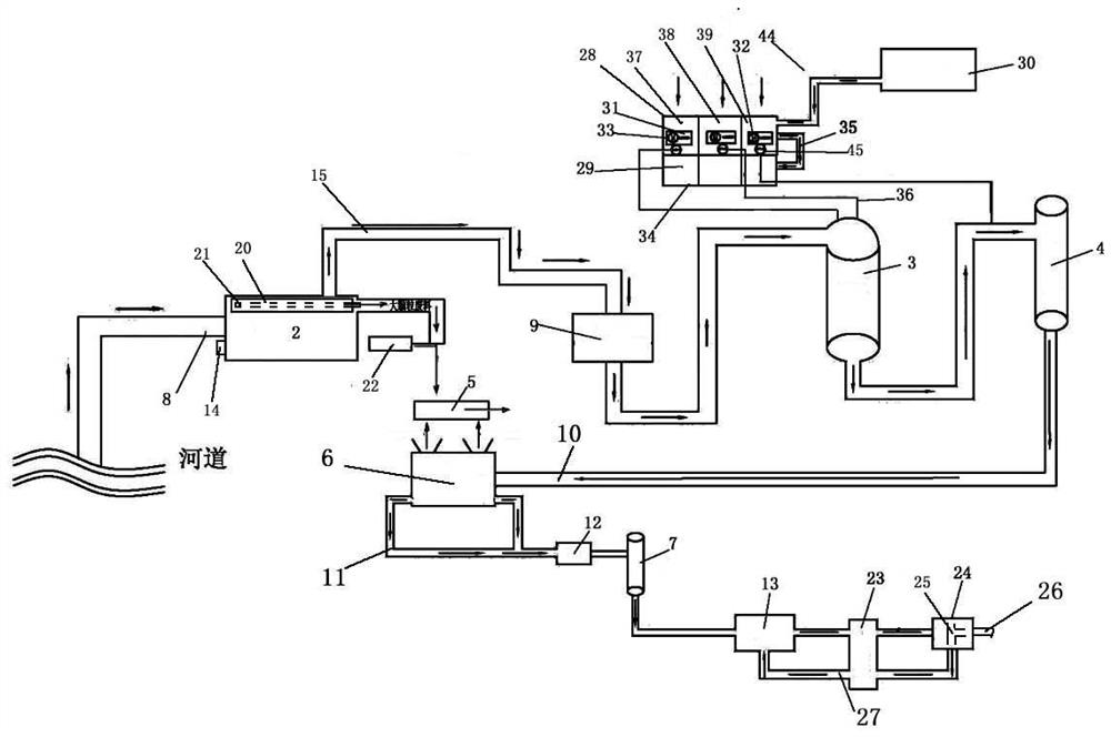
[0013] The present invention will be described in detail below in conjunction with accompanying drawing: Figure 1-3 As shown, a vehicle-mounted mobile multifunctional sludge treatment vehicle according to the present invention includes a vehicle body 1 with wheels, and the vehicle body 1 is respectively provided with a coarse filter device 2, a mixing tank 3, and a flocculation tank 4 , conveyor belt 5, main engine 6, filter 7, the front of the coarse filter 2 is connected to the external sewage suction port 8, and one end of the rear is connected to the conveyor belt 5 to transmit the large particle mud, and the other end passes through the rotor pump 9 to remove the remaining Part of the small particle mud is pumped into the mixing tank 3. The rear of the mixing tank 3 is connected to the flocculation tank 4 and the main machine 6 in turn. One side of the main machine 6 is provided with a sewage outlet 10, and the two sides of the bottom are respectively provided with draina...


PUM


Abstract

The invention provides a vehicle-mounted movable multifunctional sludge treatment vehicle, which comprises a vehicle body with wheels, wherein a rough filtration device, a mixing tank, a flocculationtank, a conveying belt, a main machine and a filter are arranged on the vehicle body, the front portion of the rough filtration device is connected with an external sewage suction port, the rear end of the rough filtration device is connected with the conveying belt to convey out large-particle sludge, the other end of the rough filtration device sucks the remaining small-particle sludge into themixing tank through a rotor pump, the flocculation tank and the main machine are sequentially connected behind the mixing tank, a sludge outlet is formed in one side of the main machine, water outletsare formed in the two sides of the bottom of the main machine respectively, and the sludge outlet is directly communicated with the conveying belt and can be used for extruding flocculated sludge into sludge blocks and then conveying the sludge blocks out. According to the invention, the sludge clearing and transporting cost can be reduced, behaviors such as secret discharge, random dumping and the like in the operation process are reduced, and the subsequent maintenance cost is reduced; and green and environment-friendly development of the industry is promoted, personnel descending and cleaning are reduced, and on-site safe operation is facilitated.

Description

technical field [0001] The invention is designed as a vehicle-mounted mobile multifunctional sludge treatment vehicle, which belongs to the field of sludge treatment. Background technique [0002] Sludge is a common kind of environmental pollution, especially after the rain, and after the construction work is completed, a large amount of sludge mixed with rainwater will be produced on the construction site or muddy ground. At present, the municipal industry uses a single-function pipeline dredging vehicle, Pipeline dredging, sewage suction trucks, manual cleaning, sludge removal vehicles, etc. to achieve pipeline dredging, sewage sludge dredging, and then transport the sludge and sewage to a fixed sludge treatment station for dehydration treatment. This treatment method requires a lot of Manual intervention, and the processing time is relatively long, which is extremely inconvenient, time-consuming and expensive, and dangers often occur during the artificial cleaning process...

Claims


Application Information

Patent Timeline
Patent Type & Authority Applications(China)
IPC IPC(8): C02F11/121C02F11/143C02F11/147
CPCC02F11/143C02F11/147C02F11/121
Inventor 吴直军
Owner 杭州诚臻工程机械有限公司
Learn More