A safety alarm device for production monitoring

A safety alarm device and siren technology, applied in the direction of alarms, instruments, closed-circuit television systems, etc., can solve problems such as the inability to guarantee the physical safety of staff, the lack of protective inspection functions, and the increase in surrounding damage, so as to achieve follow-up maintenance Ease of work, smooth movement, and reduced damage to the surroundings

Active Publication Date: 2022-06-28
江苏爱察信息技术有限公司
View PDF3 Cites 0 Cited by
  • Summary
  • Abstract
  • Description
  • Claims
  • Application Information

AI Technical Summary

Problems solved by technology

[0002] A typical production monitoring system is mainly composed of front-end equipment and back-end equipment. The front-end equipment is usually composed of a camera, manual or electric lens, pan / tilt, protective cover, multi-function decoder and other components. And through wired, wireless or optical fiber transmission media, establish corresponding connections with various equipment of the central control system (transmitting video / audio signals and control and alarm signals). In the actual production monitoring system, these front-end equipment may not be used at the same time. However, the lens to realize the image acquisition of the monitoring site is indispensable. The back-end equipment can be further divided into central control equipment and sub-control equipment. Since most of the existing production equipment does not have the function of protective inspection, it increases the internal failure of the production platform. The damage to the surroundings caused the inability to guarantee the physical safety of the staff, increased the blockage during the product transportation, brought inconvenience to the user's follow-up maintenance work, and brought certain adverse effects to the actual use. Therefore, needs to be improved

Method used


Image

  • A safety alarm device for production monitoring
  • A safety alarm device for production monitoring
  • A safety alarm device for production monitoring

Examples


Embodiment Construction

[0019] The technical solutions in the embodiments of the present invention will be clearly and completely described below with reference to the accompanying drawings in the embodiments of the present invention. Obviously, the described embodiments are only a part of the embodiments of the present invention, but not all of the embodiments. Based on the embodiments of the present invention, all other embodiments obtained by those of ordinary skill in the art without creative efforts shall fall within the protection scope of the present invention.

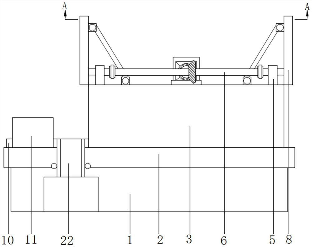
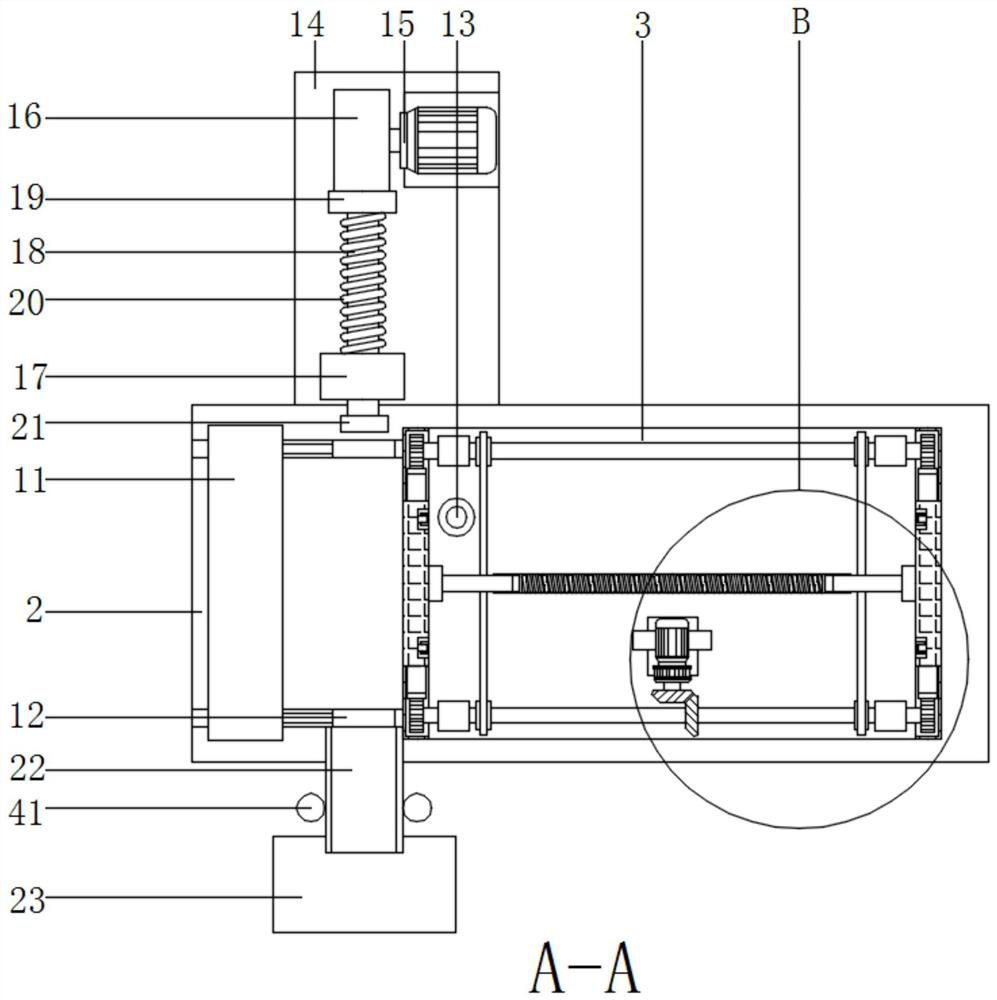
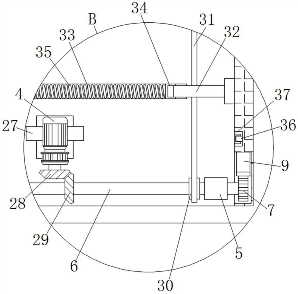
[0020] see Figure 1 to Figure 5 , the present invention provides a technical solution: a safety alarm device for production monitoring, comprising a support leg 1, a workbench 2 is fixedly connected to the surface of the support leg 1, and a production platform is fixedly connected to the surface of the workbench 2 near its right side 3. On the surface of the production table 3 near the bottom thereof, a driver 1 4 is fixedly install...


PUM


Abstract

The invention discloses a safety alarm device for production monitoring, which comprises a support leg, the surface of the support leg is fixedly connected with a workbench, and the surface near the right side of the workbench is fixedly connected with a production platform, and the production platform The surface close to the bottom of the upper surface is fixedly installed with a driving machine 1 through a bracket, the output end of the driving machine 1 is fixedly connected with a reversing assembly, and the surface near the circumference of the production table is fixedly connected with four fixed plates. Through the cooperation of the above-mentioned structures, the invention realizes the protection of the production platform for the user, reduces the damage to the surrounding area when there is a failure inside the production platform, ensures the physical safety of the staff, and ensures the safety of the workbench during the maintenance of the production platform. The products on the board can be temporarily stored, which reduces the jam during product transportation and brings convenience to the user's follow-up maintenance work.

Description

technical field [0001] The invention relates to the related technical field of production monitoring, in particular to a safety alarm device for production monitoring. Background technique [0002] A typical production monitoring system is mainly composed of front-end equipment and back-end equipment. The front-end equipment is usually composed of cameras, manual or motorized lenses, PTZs, protective covers, multi-function decoders and other components, each of which performs its own duties. And through wired, wireless or optical fiber transmission media to establish corresponding connections with various equipment in the central control system (transmission of video / audio signals and control, alarm signals), in the actual production monitoring system, these front-end equipment may not be used at the same time. However, the lens for monitoring the scene image acquisition is essential, and the back-end equipment can be further divided into central control equipment and sub-co...

Claims


Application Information

Patent Timeline
Patent Type & Authority Patents(China)
IPC IPC(8): H04N7/18G08B21/18
CPCH04N7/18G08B21/18
Inventor 李金超
Owner 江苏爱察信息技术有限公司
Why Eureka
Try Eureka