
Generator transformer and power generation system

A power generation system and transformer technology, applied in the direction of transformers, transformer/inductor magnetic cores, transformer/inductor components, etc., can solve problems such as difficult to meet steam turbine generator sets, achieve far-reaching economic and social benefits, and huge costs Advantages, the effect of reducing magnetic flux leakage

Pending Publication Date: 2021-02-26
TBEA HENGYANG TRANSFORMERS
View PDF0 Cites 0 Cited by
  • Summary
  • Abstract
  • Description
  • Claims
  • Application Information

AI Technical Summary

Problems solved by technology

At present, the maximum three-phase capacity of a 500KV voltage level transformer is 1230MVA, which is difficult to meet the needs of a higher capacity such as a 1350MW turbogenerator set. The development of super-large capacity transformers has become an urgent need for domestic and foreign transformer manufacturers.

Method used


Image

  • Generator transformer and power generation system
  • Generator transformer and power generation system
  • Generator transformer and power generation system

Examples


Embodiment 1

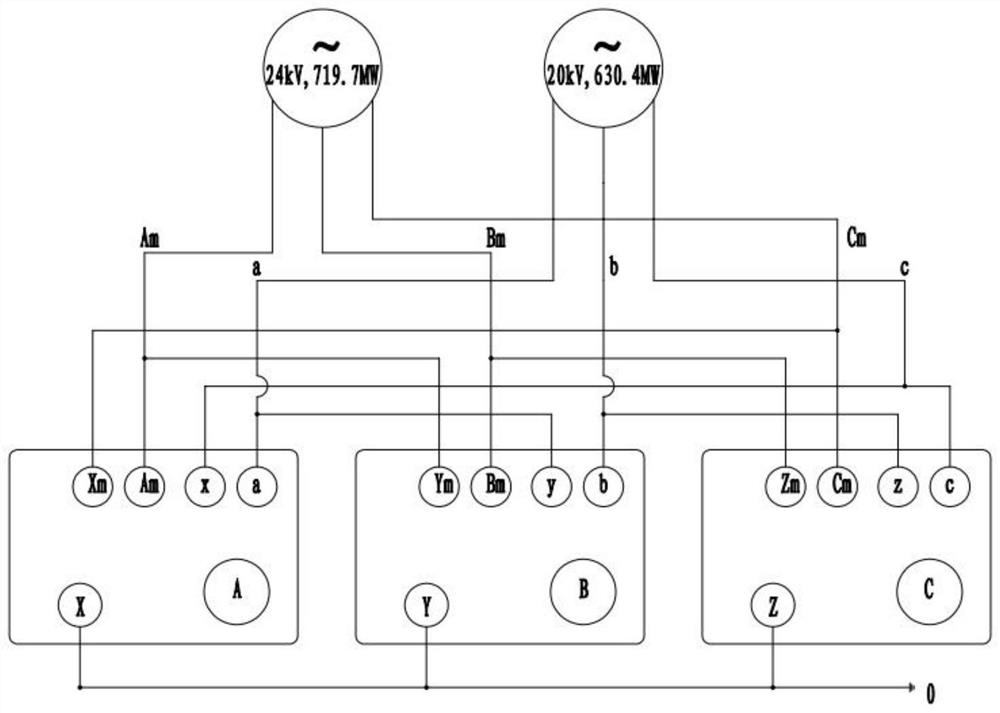
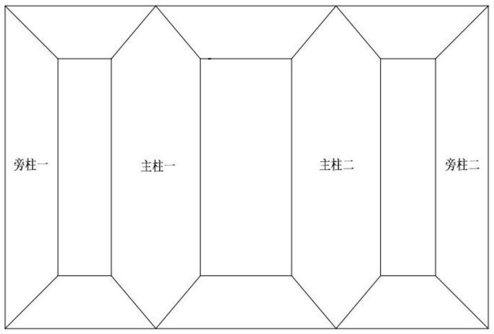
[0027] Such as figure 1 As shown, the generator transformer is a three-phase split structure, which is composed of three single-phase transformers. The iron core of any single-phase transformer is a four-column structure, two main columns and two side columns.

[0028] Such as image 3 As shown, the high-voltage coil 1 7 and the low-voltage coil 1 2 are arranged on the main column 1 core, and the high-voltage coil 2 16 and the low-voltage coil 2 11 are arranged on the main column 2 iron core.

[0029] According to the capacity and output voltage of the generator set, the capacity of main column 1 and main column 2 can be set, as well as the voltage of low-voltage coil 1 and low-voltage coil 2. Low-voltage coil 1 and low-voltage coil 2 can be connected to different capacities and output voltage levels generator set.

[0030] Such as Figure 4 The generator coil structure shown includes coil assembly structure 1 and coil assembly structure 2; coil assembly structure 1 is comp...

Embodiment 2

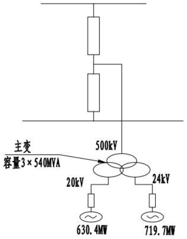
[0040] On the basis of the above embodiments, the present invention also provides a power generation system, see figure 2 , the power generation system includes 2 generator sets and the above-mentioned generator transformer, and the transformer is connected to the generator set and the power grid.

[0041] Specifically, the low-voltage side of the transformer is connected to the generator set, and the high-voltage side of the transformer is connected to the grid, which is used to convert the voltage of the generator set and output it to the grid for use by users.

[0042] The above-mentioned power generation system can greatly reduce the construction cost of the power station due to the adoption of the above-mentioned generator transformer, has a huge cost advantage, and at the same time occupies a smaller area.


PUM


Abstract

The invention provides a generator transformer and a power generation system, in particular to a three-phase split type transformer. According to the invention, a coil structure meets the technical requirement of a unit for secondary reheating. The generator transformer is formed by connecting three single-phase transformers, wherein an iron core of each single-phase transformer is of a four-column structure, namely two main column iron cores and two side column iron cores; each main column iron core is provided with a high-voltage coil and a low-voltage coil, and the capacities of the two columns are 300 MVA and 240 MVA respectively; the two high-voltage coils are both of an inner shielding continuous structure, the head ends of the two high-voltage coils are hand in hand at the middle portions of the coils and are then parallelly led out, the tail ends of the two high-voltage coils are hand in hand at the upper and lower portions of the coils and are then parallelly led out, and voltage-regulating branching line segments are arranged at the middle portions of the high-voltage coils; and the two low-voltage coils are of a double-layer spiral structure and are respectively and independently led out. Under the same generator set condition, the transformer of the invention is configured according to a conventional transformer and has a huge cost advantage and a smaller occupied area.

Description

technical field [0001] The invention belongs to the technical field of power transformers, and in particular relates to a generator transformer applied to the arrangement of ultra-supercritical double reheating high and low units and a power generation system using the transformer. Background technique [0002] With the continuous development of my country's electric power industry, especially under the tremendous pressure of continuous improvement of the atmospheric environment and the continuous reduction of CO2 emissions in response to climate change, the demand for thermal power generation equipment is towards larger capacity, higher parameters, higher efficiency, lower consumption, and lower pollution. And develop in a more intelligent direction. The development of ultra-supercritical technology from 600°C to 700°C and from primary reheating to secondary reheating is an inevitable trend, and the demand for larger-capacity generator transformers is also increasing. [...

Claims


Application Information

Patent Timeline
Patent Type & Authority Applications(China)
IPC IPC(8): H01F30/12H01F30/10H01F27/24H01F27/28H01F27/29H01F27/30H01F27/04H01F27/34
CPCH01F27/04H01F27/24H01F27/2823H01F27/2828H01F27/29H01F27/306H01F27/346H01F30/10H01F30/12
Inventor 刘金波何海江田国华宁澔如张忠民付丛邸林涛陆帅段成陈伦伦黄彪肖长河
Owner TBEA HENGYANG TRANSFORMERS
Learn More