Plate heat exchanger

A technology of plate heat exchangers and plates, applied in the direction of indirect heat exchangers, heat exchanger types, heat exchange equipment, etc., can solve the unfavorable weight and volume of heat exchanger products, increase the resistance of fluid flowing through the flow channel, and the fluid Problems such as small flow resistance can improve heat transfer and transportation, expand effective cross-sectional area, and achieve good heat transfer performance.

Active Publication Date: 2022-06-21
ZHEJIANG SANHUA INTELLIGENT CONTROLS CO LTD
View PDF0 Cites 0 Cited by
  • Summary
  • Abstract
  • Description
  • Claims
  • Application Information

AI Technical Summary

Problems solved by technology

[0003] like Figure 22 As shown, some technologies adopt a fin structure to disturb and block the fluid in the direction of fluid flow, so as to obtain a better heat exchange effect, but at the same time, it also increases the resistance of the fluid flowing through the flow channel. Correspondingly, it is required pay more pump power
There are also some technologies that adopt a wavy curved fin structure in order to reduce the flow resistance, and extend the troughs of the wavy fins along the direction of fluid flow, so that the fluid can easily flow through the wavy fins formed by the troughs channel, the fluid flow resistance is small, but the heat transfer effect is not good
[0004] Therefore, the relevant plate heat exchanger technology is to balance the two technical indicators of heat transfer performance and fluid pressure drop. For application scenarios with relatively high requirements for heat transfer performance and fluid pressure drop, the number of flow channels has to be considered The increase of the fin size, the expansion of the plate size, etc., not only increases the cost, but also is not conducive to the weight and volume of the heat exchanger product, so the related technology still needs to be improved

Method used


Image

  • Plate heat exchanger
  • Plate heat exchanger
  • Plate heat exchanger

Examples


Embodiment Construction

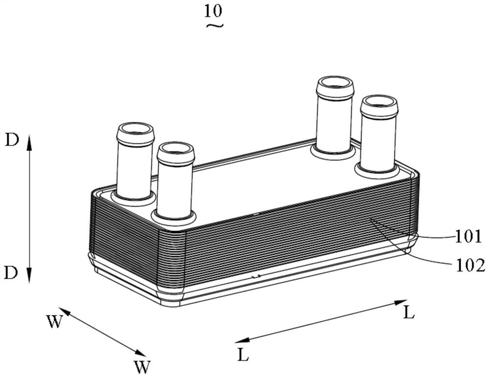
[0033] refer to figure 1 , the present application provides a plate heat exchanger 10, which includes several plates and at least one fin plate 60. Specifically, the fin plate 60 can be fixed between the two plates by brazing. The several plates include a first plate 101 and a second plate 102, and the number of the first plate 101 and the second plate 102 may be multiple. Of course, the plate heat exchanger 10 may also include other third, fourth, fifth plates, etc. which are different in structure from the first plate 101 and the second plate 102 .

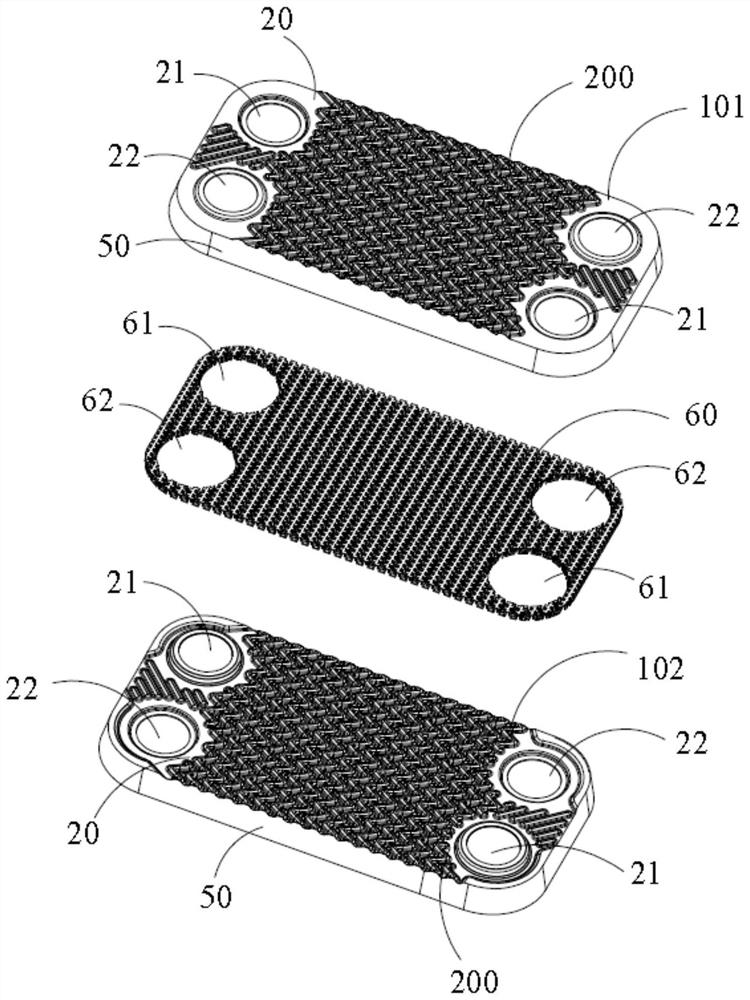
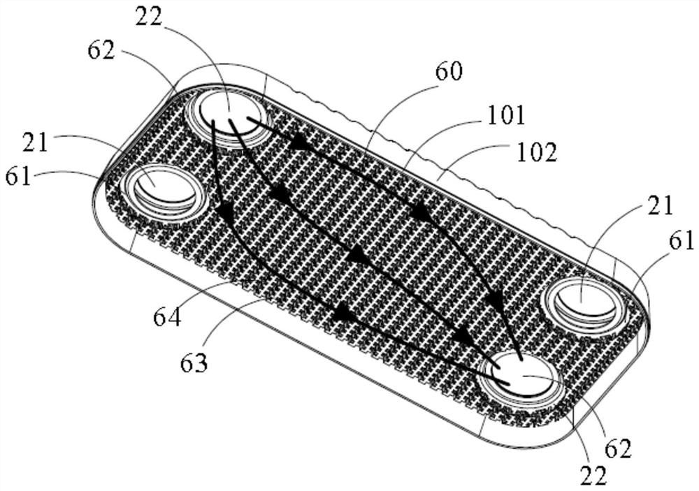
[0034] In some embodiments, refer to figure 2 , the fin plate 60 is located between the reverse surface 300 of the first plate 101 and the front surface 200 of the second plate 102 . The reverse side of the plate 300 figure 2 not shown, refer to Figure 4 As shown in the exploded schematic diagram, the fin plate 60 can increase the heat exchange area of ​​the fluid flowing between the reverse surface 300 of the first plat...


PUM


Abstract

The application discloses a plate heat exchanger, which includes at least one finned plate and several plates; the finned plate is located between two adjacent plates; the finned plate includes a base and several finned plates arranged along the first direction Fin units; each fin unit includes a plurality of first fins and a plurality of second fins; each fin includes a top and two side portions; at least one set of side portions located on the top side of the first fin and the side portion located on the top side of the second fin are misaligned along the second direction, so that in the group of side portions respectively belonging to adjacent first fins and second fins, a Window; at least one of the plates is provided with several corrugated protrusions, a groove is formed between two adjacent corrugated protrusions, and the opening of the groove faces the side where the finned plate is located; the top of the corrugated protrusions is at least partly The area is in contact with the finned plate and the window communicates with the groove. The plate heat exchanger of the present application is beneficial to reduce the flow pressure drop while improving the heat exchange performance.

Description

technical field [0001] The present application relates to the technical field of heat exchange, and in particular, to a plate heat exchanger. Background technique [0002] The plate heat exchanger in the related art includes structures such as plates and fins. Fins are usually located between two adjacent plates, and fins are arranged in the flow channel formed by the plates, or focus on low flow resistance, or focus on good heat exchange performance, usually in two types of low flow resistance and good heat exchange. Make a balance or take between the technical effects. [0003] like Figure 22 As shown in the figure, some technologies adopt the fin structure to disturb and block the fluid in the direction of fluid flow, so as to obtain a better heat exchange effect, but at the same time, it also increases the resistance of the fluid flowing through the flow channel. Correspondingly, it is necessary to Pay more pump work. In some other technologies, in order to reduce th...

Claims


Application Information

Patent Timeline
Patent Type & Authority Patents(China)
IPC IPC(8): F28D9/04F28F3/04
CPCF28D9/04F28F3/046
Inventor 李华邵汉李永平郑希茹
Owner ZHEJIANG SANHUA INTELLIGENT CONTROLS CO LTD
Why Eureka
Try Eureka