Synchronous bearing and electric shaft driving system of vehicle

A drive system and bearing technology, applied in the direction of shafts and bearings, bearing components, vehicle parts, etc., can solve the problems of low reliability and easy damage, and achieve the effects of convenient operation, stable torque transmission or cutting process, and simple structure

Pending Publication Date: 2021-02-26
SCHAEFFLER TECH AG & CO KG
View PDF0 Cites 0 Cited by
  • Summary
  • Abstract
  • Description
  • Claims
  • Application Information

AI Technical Summary

Problems solved by technology

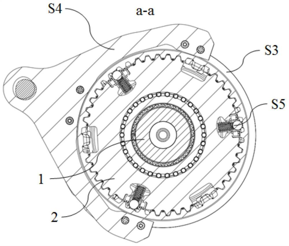
[0011] (vi) Among the sub-components included in the synchronizer S, there are easily damaged parts, such as the springs and steel balls included in the slider S5, which are easily damaged and have low reliability

Method used


Image

  • Synchronous bearing and electric shaft driving system of vehicle
  • Synchronous bearing and electric shaft driving system of vehicle
  • Synchronous bearing and electric shaft driving system of vehicle

Examples


Embodiment Construction

[0052] Exemplary embodiments of the present invention are described below with reference to the accompanying drawings. It should be understood that these specific descriptions are only used to teach those skilled in the art how to implement the present invention, but are not intended to exhaust all possible ways of the present invention, nor are they intended to limit the scope of the present invention.

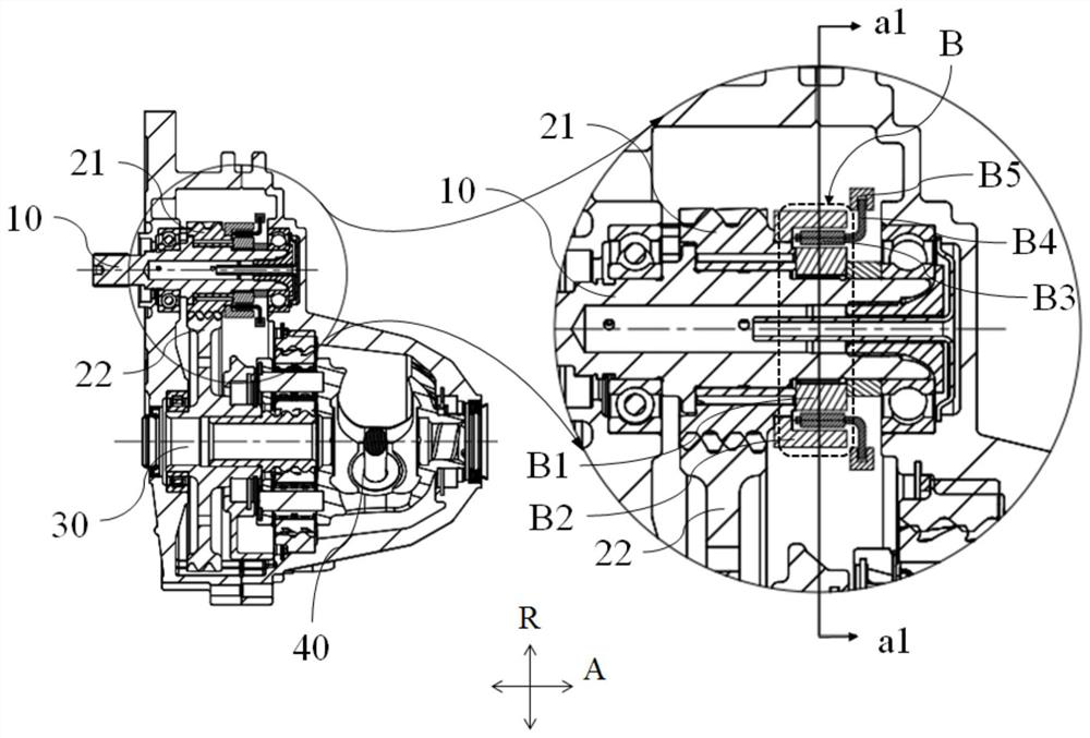
[0053] The present invention uses a bearing assembly (hereinafter referred to as synchronous bearing) to replace the synchronizer in the transmission of the prior art, so that the shifting process of the transmission can be carried out smoothly. Refer below Figure 3 to Figure 5 A synchronous bearing and electric shaft drive system according to the present invention is introduced.

[0054] Unless otherwise specified, refer to image 3 , A represents the axial direction of the synchronous bearing, and the axial direction A is consistent with the axial direction of the input ...


PUM


Abstract

The invention provides a synchronous bearing and an electric shaft driving system of a vehicle. The synchronous bearing (B) comprises an inner ring (B1), an outer ring (B2), rolling bodies (B3) and aretainer (B4), the outer circumferential surface of the inner ring (B1) is sunken towards the radial inner side to define a plurality of grooves (G), the rolling bodies (B3) are accommodated in the grooves (G), the grooves (G) are provided with deep parts (G1) and shallow parts (G2, G3) with different radial depths, the retainer (B4) can abut against the inner ring (B1) to move in the axial direction and the circumferential direction at the same time, the rolling bodies (B3) move between the deep portion (G1) and the shallow portions (G2, G3), and therefore the rolling bodies (B3) can roll freely or be locked by the inner ring (B1) and the outer ring (B2). According to the synchronous bearing, the structure is simple, operation is convenient, and the torque transmission or cut-off processof an input shaft and an output shaft can be stably conducted.

Description

technical field [0001] The present invention relates to the field of motor vehicles, in particular to the field of transmissions for vehicles, especially the electric shaft drive system in pure electric vehicles or hybrid vehicles, and more specifically to the electric shaft drive system used to realize the input shaft and output shaft. Synchronized synchronous bearings and the electric shaft drive system of the vehicle. Background technique [0002] In the prior art, a synchronizer is usually used to improve the shifting performance of the transmission of a motor vehicle. The synchronizer can put the input shaft and the shifting gear at the same rotational speed (ie, rotational speed synchronization), and put them in anti-rotation after the synchronization. way of coupling. [0003] For electric vehicles, including pure electric vehicles and hybrid (oil-electric hybrid) vehicles, their electric drive methods include central motor drive and hub motor drive. A common arrang...

Claims


Application Information

Patent Timeline
Patent Type & Authority Applications(China)
IPC IPC(8): F16H3/02F16D23/02F16C33/58B60K17/12
CPCB60K17/12F16C33/581F16D23/02F16H3/003F16H3/02F16H2200/003F16H2200/0082F16H2200/2033
Inventor 俞正才
Owner SCHAEFFLER TECH AG & CO KG
Why Eureka
Try Eureka