
Sewage pump

A technology for sewage pumps and pump casings, applied in the direction of pumps, pump control, pump components, etc., can solve the problems affecting the progress of the project, reduce the working efficiency of sewage pumps, slow down the flow rate, etc., and achieve the effect of saving manpower

Inactive Publication Date: 2021-02-26
张文波
View PDF0 Cites 1 Cited by
  • Summary
  • Abstract
  • Description
  • Claims
  • Application Information

AI Technical Summary

Problems solved by technology

The sewage pump needs to install a filter screen at the water inlet. Since the working medium of the sewage pump has more impurities, there will be more impurities on the filter screen over time, which will reduce the water flow in the pipeline and slow down the flow rate, resulting in the working efficiency of the sewage pump. Reduced, air suction phenomenon occurs, and the filter screen is often cleaned manually, which will waste a lot of manpower and material resources, and will also affect the progress of the project

Method used


Image

  • Sewage pump
  • Sewage pump
  • Sewage pump

Examples


Embodiment Construction

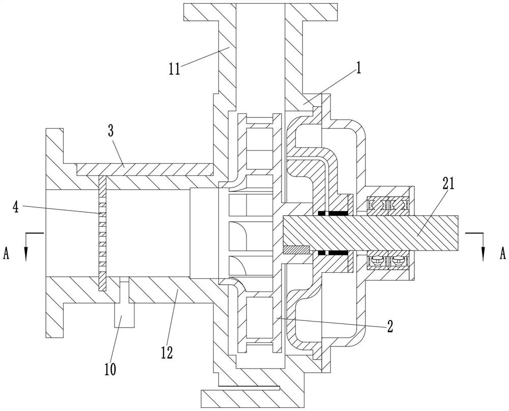
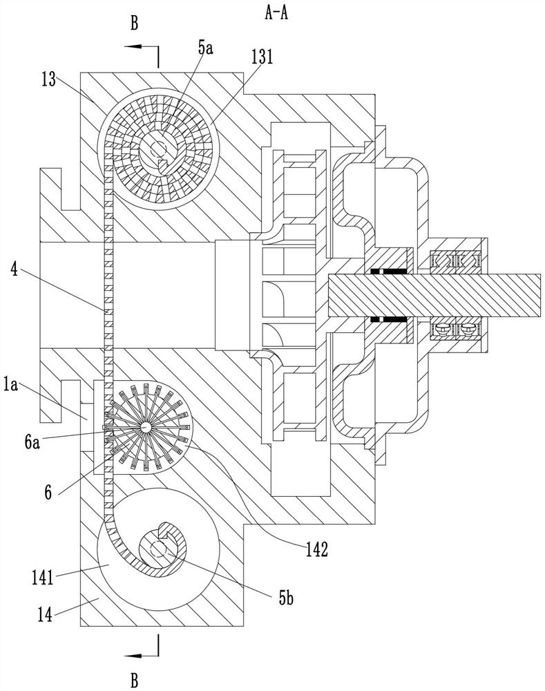
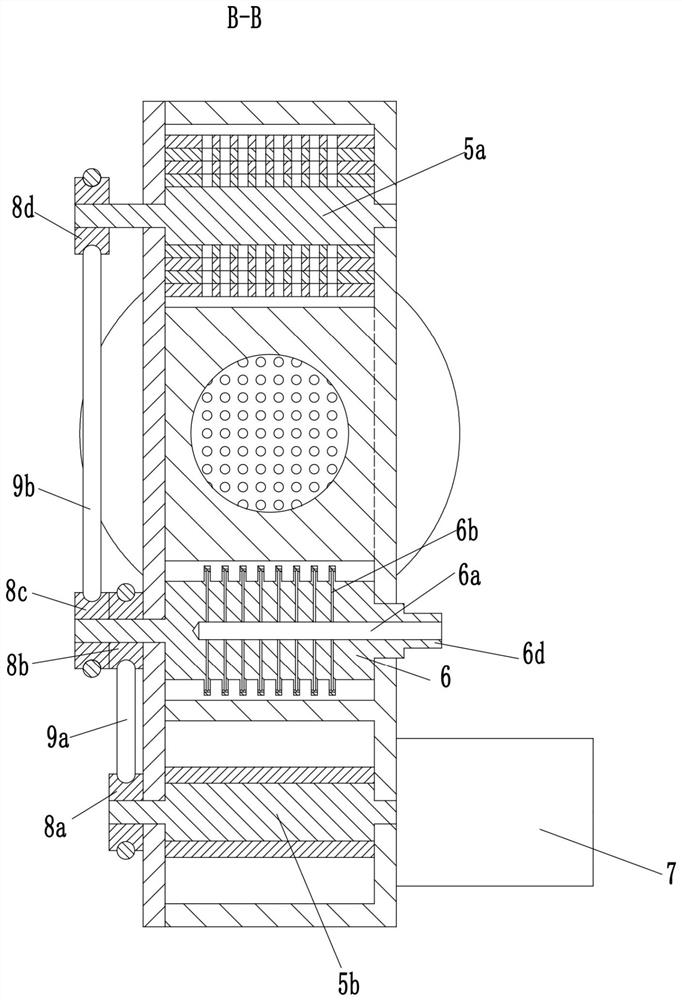
[0019] see Figure 1-4 As shown, the present invention provides a sewage pump, including a pump casing 1, an impeller 2 is arranged inside the pump casing 1, and a power unit fixedly connected with the impeller 2 is provided on the right side of the pump casing 1 to drive the impeller 2 to rotate. shaft 21; the outer side of the pump casing 1 is provided with an outlet pipe 11 along the radial direction of the impeller 2, and an inlet pipe 12 coaxial with the power shaft 21 is provided along the axial direction of the impeller 2; The first bump 13 and the second bump 14 are respectively provided on both sides of the two sides, and the inside of the first bump 13 is provided with a first turning groove 131 along the axial direction perpendicular to the inlet pipe 12, and the inside of the second bump 14 is A second turning groove 141 is arranged perpendicular to the axial direction of the inlet pipe 12, and a third turning groove 142 is arranged between the second turning groov...


PUM


Abstract

The invention discloses a sewage pump. The sewage pump comprises a pump shell, wherein an impeller is arranged in the pump shell, and a power shaft is arranged on the right side of the pump shell; anoutlet pipe and an inlet pipe are arranged on the outer side of the pump shell; a first protruding block and a second protruding block are arranged on the portions, on two sides of the inlet pipe, ofthe pump body respectively, a first rotating groove is formed in the first protruding block, and a second rotating groove and a third rotating groove are formed in the second protruding block; the first protruding block and the second protruding block are provided with cover plates covering the first rotating groove, the second rotating groove and the third rotating groove; a first rolling shaft is rotatably connected in the first rotating groove, a second rolling shaft is rotatably connected in the second rotating groove, and a filtering belt penetrating through the third rotating groove andthe inlet pipe is wound between the first rolling shaft and the second rolling shaft; and a cleaning assembly is arranged in the third rotating groove, and a motor is fixedly mounted on the second protruding block. The sewage pump not only is simple in structure, but also can clean the filtering belt automatically.

Description

technical field [0001] The invention belongs to the field of sewage pumps, in particular to a sewage pump. Background technique [0002] The structure of the existing sewage pump includes a motor, an impeller and a pump casing, and a water inlet and a water outlet arranged on the pump casing. The impeller is arranged in the pump casing and connected with the rotating shaft of the motor. The sewage pump needs to install a filter screen at the water inlet. Since the working medium of the sewage pump has more impurities, there will be more impurities on the filter screen over time, which will reduce the water flow in the pipeline and slow down the flow rate, resulting in the working efficiency of the sewage pump. reduce, resulting in air suction, and often need to manually clean the filter, which will waste a lot of manpower and material resources, and will also affect the progress of the project. Contents of the invention [0003] The object of the present invention is to p...

Claims


Application Information

Patent Timeline
Patent Type & Authority Applications(China)
IPC IPC(8): F04D7/00F04D29/70F04D15/00
CPCF04D7/00F04D15/0077F04D29/708
Inventor 张文波赵宪长张丽丽
Owner 张文波
Learn More