Compact bearing high-pressure jet grouting drill bit

A technology of high-pressure rotary spraying and composite sheet, which is applied in the direction of drill bits, drilling with liquid/gas jets, drill pipes, etc. It can solve the problems of inconvenient removal of drill bits and slow drilling speed, etc., so as to improve the cutting rate and effect, improve the effect, Simple and reasonable structure

Pending Publication Date: 2021-02-26
史彦
View PDF0 Cites 0 Cited by
  • Summary
  • Abstract
  • Description
  • Claims
  • Application Information

AI Technical Summary

Problems solved by technology

[0003] In order to solve the above-mentioned technical problems, the present invention provides a technical field related to jet jet drilling equipment, which adopts jet jet composite high-pressure cutting head to improve the cutting effect of the drill bit, and through coaxial and non-concentric cutting nozzles, it can simultaneously The side wall and end of the hole are sprayed with high pressure, which is convenient for drilling the side wall and expanding the bottom end of the drill bit, which solves the problems of slow drilling speed and inconvenient removal of the drill bit

Method used


Image

  • Compact bearing high-pressure jet grouting drill bit
  • Compact bearing high-pressure jet grouting drill bit
  • Compact bearing high-pressure jet grouting drill bit

Examples


Embodiment

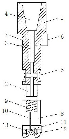
[0024] combine Figure 1-4 , The present invention is a high-pressure jet jet drill bit with a composite sheet bearing, including a drill pipe body 1 and a drill bit body 8 . The drill pipe body 1 is in the shape of a shaft. The bottom of the drill pipe body 1 is fixed with a connecting block 2, and the drill pipe body 1 and the connecting block 2 are integrally cast. The stability between the drill pipe body 1 and the connection block 2 is strengthened. A rotary jet water delivery channel 3 is opened at the center of the inside of the drill pipe body 1 , and the bottom end of the rotary jet water delivery channel 3 runs through the connecting block 2 . The top end of the drill pipe body 1 is provided with a conical interface 4, and the bottom of the conical interface 4 communicates with the rotary jet water delivery channel 3. The bottom of the outer side of the drill pipe body 1 is symmetrically provided with side nozzles 5 , and the side nozzles 5 communicate with the ro...


PUM

PropertyMeasurementUnit
Thicknessaaaaaaaaaa

Abstract

The invention discloses a compact bearing high-pressure jet grouting drill bit. The compact bearing high-pressure jet grouting drill bit comprises a drill rod body and a drill bit body. The drill rodbody is of a shaft-shaped structure. A connecting block is fixed to the bottom of the drill rod body, and the drill rod body and the connecting block are integrally formed through casting. A jet grouting water conveying channel is formed in the center of the interior of the drill rod body. The compact bearing high-pressure jet grouting drill bit is simple and reasonable in structure, jet groutingcutting at the drilling position can be achieved through the arrangement of a jet grouting compact high-pressure cutting tool bit and a nozzle at the front end of the drill bit body, a first cutting tool bit and a second cutting tool bit are used in cooperation, the first cutting tool bit cuts the outer ring of the drilling position, the second cutting tool bit cuts the inner ring of the drillingposition, and therefore the cutting speed and effect during drilling are improved; and due to the arrangement of a lateral nozzle on the outer side of the drill rod body and a nozzle at the front end,a coaxial and non-concentric cutting nozzle process is adopted, high-pressure jet cutting can be conducted on the side wall of a drilled hole and the front end of a drill bit at the same time, and the high-pressure jet grouting effect is improved.

Description

technical field [0001] The invention relates to the technical field of jet-jet drilling equipment, in particular to a high-pressure jet-jet drill bit with a composite sheet bearing. Background technique [0002] In recent years, with the rapid development of national capital construction projects, the construction scale of railways, highways, airports, docks and high-rise buildings has continued to expand, and the quality requirements for foundation treatment, foundation pit support and foundation pit water sealing have continued to increase. The spray pile technology has the advantages of simple equipment, convenient construction, fast speed, material saving, high efficiency, low cost, simple operation, and wide application range, and is widely used in many infrastructure fields. The rotary grouting drilling rig is a special equipment for the construction of rotary grouting piles. It uses media such as slurry, compressed air, and clean water to perform rotary grouting with ...

Claims


Application Information

Patent Timeline
IPC IPC(8): E21B7/28E21B7/18E21B17/00E21B17/042E21B10/43E21B10/60E21B17/10E21B10/54
CPCE21B7/18E21B7/28E21B10/43E21B10/54E21B10/602E21B17/00E21B17/006E21B17/042E21B17/1085
Inventor 史彦
Owner 史彦
Why Eureka
Try Eureka