Reinforcement reinforcement method and system for foundation anchor bolts of power transmission tower

A technology for transmission towers and anchor bolts, applied in the field of transmission tower foundations, can solve the problems of repairing cracks and cannot fundamentally suppress cracks, and achieves the effect of inhibiting lateral development, good force transmission, and toughness.

Inactive Publication Date: 2021-02-26
STATE GRID SICHUAN ELECTRIC POWER CORP ELECTRIC POWER RES INST
View PDF6 Cites 0 Cited by
  • Summary
  • Abstract
  • Description
  • Claims
  • Application Information

AI Technical Summary

Problems solved by technology

[0006] The purpose of the present invention is to provide a reinforcement method and system for the anchor bolts of the foundation of the transmission tower, which solves the problem that the existing methods for repairing cracks cannot fundamentally suppress the cracks, and has the advantage of simple construction and operation

Method used


Image

  • Reinforcement reinforcement method and system for foundation anchor bolts of power transmission tower
  • Reinforcement reinforcement method and system for foundation anchor bolts of power transmission tower
  • Reinforcement reinforcement method and system for foundation anchor bolts of power transmission tower

Examples


Embodiment 1

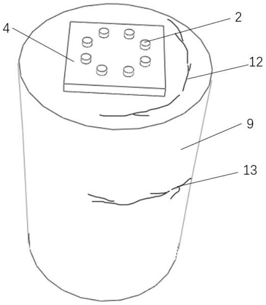
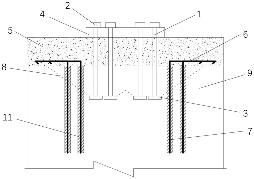
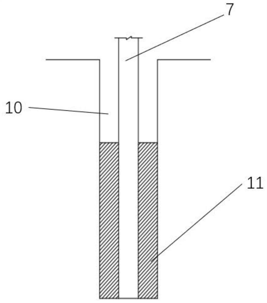
[0038] Such as Figure 1-Figure 4 As shown, a reinforcement system for the foundation anchor bolt of a transmission tower includes a concrete pile foundation 9, and the center of the concrete pile foundation 9 is provided with a plurality of anchor rods 1 in the axial direction, and the plurality of anchor rods 1 form an anchor bolt group, the bottom of the anchor rod 1 is provided with an anchor plate 3, the top of the anchor rod 1 passes through the through hole on the backing plate 4 of the anchor bolt group, the top of the anchor rod 1 is tightened by a nut 2, and includes Several L-shaped steel bars, several L-shaped steel bars are evenly arranged in two circles around the anchor bolt group, and the L-shaped steel bars include mutually perpendicular steel bar horizontal sections 6 and steel bar vertical sections 7. Extend and insert into the channel 10 in the concrete pile foundation 9, the channel 10 is filled with epoxy resin glue 11, the vertical section 7 of the steel...

Embodiment 2

[0047] Such as Figure 1-Figure 4 As shown, this embodiment is based on Embodiment 1. When there is an annular crack 12 on the pile foundation upper surface in the concrete pile foundation 9, the concrete on the top of the concrete pile foundation 9 is excavated first, and then the concrete pile foundation 9 is drilled along the axial direction. The hole forms a channel 10, and then the vertical section 7 of the steel bar is arranged in the channel 10, and the top of the concrete pile foundation 9 is backfilled to form a backfilled concrete 5, and the horizontal section 6 of the steel bar is embedded in the backfilled concrete 5.

[0048] This embodiment is applicable to when the concrete pile foundation 9 has an annular crack 12 on the upper surface of the pile foundation and an annular crack 13 on the side of the pile foundation, the construction method includes the following steps:

[0049] S1, excavate the upper surface concrete of the concrete pile foundation 9 according ...


PUM


Abstract

The invention discloses a reinforcement reinforcement method and system for foundation anchor bolts of a power transmission tower. The reinforcement system comprises a concrete pile foundation, a plurality of anchor rods are arranged in the center of the concrete pile foundation in the axial direction, the anchor rods form an anchor bolt group, the reinforcement system further comprises a plurality of L-shaped steel bars, the L-shaped steel bars are annularly and evenly arranged with the anchor bolt group as the center, and the L-shaped steel bars are connected with the concrete pile foundation through the L-shaped steel bars. The L-shaped reinforcing steel bar comprises a reinforcing steel bar horizontal section and a reinforcing steel bar vertical section which are perpendicular to eachother, the reinforcing steel bar vertical section extends downwards to be inserted into a hole channel in the concrete pile foundation, the hole channel is filled with epoxy resin glue, the reinforcing steel bar vertical section extends downwards to exceed the fracture surface of the concrete cone by a certain length, and the exceeding part is the calculated anchoring length. The steel bar horizontal section extends outwards in the radial direction of the concrete pile foundation and has a certain anchoring length. The problem that an existing crack repairing method cannot fundamentally inhibit cracks is solved, and the method has the advantage of being simple in construction operation.

Description

technical field [0001] The invention relates to the technical field of transmission tower foundations, in particular to a reinforcement method and system for the foundation anchor bolts of transmission towers. Background technique [0002] The transmission line is an important part of the power grid. The foundation project of the transmission line tower belongs to the hidden project of the transmission line construction. The design, construction, quality inspection and other aspects are often more complicated than the upper structure. There are many hidden dangers in the operation process. It may cause serious safety accidents and economic losses. [0003] Transmission lines across mountainous areas are located at high altitudes. Due to the complex terrain conditions around them, transmission poles and towers are subjected to wind loads and ice loads, resulting in long-term wind vibrations in the line tower line system, especially under light ice conditions. Under the long-...

Claims


Application Information

Patent Timeline
Patent Type & Authority Applications(China)
IPC IPC(8): E02D27/42E02D27/50E02D37/00
CPCE02D27/42E02D27/50E02D37/00
Inventor 曹永兴卜祥航曾宏谢强罗东辉李淑琪吴驰薛志航朱军
Owner STATE GRID SICHUAN ELECTRIC POWER CORP ELECTRIC POWER RES INST
Why Eureka
Try Eureka