
Spinning roller for spinning

A textile roller and fixed block technology, which is applied in the field of textile rollers, can solve problems such as difficult disassembly and replacement, and achieve the effect of improving rotation efficiency and improving disassembly and replacement efficiency

Inactive Publication Date: 2021-02-26
湖州南浔达平纺织品有限公司
View PDF7 Cites 0 Cited by
  • Summary
  • Abstract
  • Description
  • Claims
  • Application Information

AI Technical Summary

Problems solved by technology

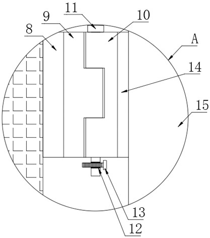
[0004] In the present invention, when the rotating concave block with the connecting rod is damaged, the knob limit inserts the upper limit bolt, and then the limiting insert is taken out at the connection between the rotating concave block and the rotating convex block, thereby replacing a new connecting rod, effectively Improve the efficiency of disassembly and replacement, aiming to solve the problem that the existing textile rollers are not easy to disassemble and replace

Method used


Image

  • Spinning roller for spinning
  • Spinning roller for spinning
  • Spinning roller for spinning

Examples


Embodiment Construction

[0020] In order to make the object, technical solution and advantages of the present invention clearer, the present invention will be further described in detail below in conjunction with the accompanying drawings and embodiments. It should be understood that the specific embodiments described here are only used to explain the present invention, not to limit the present invention.

[0021] In describing the present invention, it should be understood that the terms "length", "width", "upper", "lower", "front", "rear", "left", "right", "vertical", The orientation or positional relationship indicated by "horizontal", "top", "bottom", "inner", "outer", etc. are based on the orientation or positional relationship shown in the drawings, and are only for the convenience of describing the present invention and simplifying the description, rather than Nothing indicating or implying that a referenced device or element must have a particular orientation, be constructed, and operate in a ...


PUM


Abstract

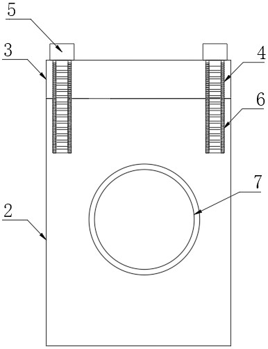
The invention discloses a spinning roller for spinning, and particularly relates to the technical field of spinning rollers. The spinning roller comprises a base, a first fixing block is arranged at the top of the base, a first mounting plate is arranged at the top of the first fixing block, mounting openings are formed in the top of the first mounting plate, mounting bolts are arranged in the mounting openings, and fixing openings are formed in the tops of the first fixing blocks. Due to the fact that a rotating concave block and a rotating convex block are movably connected in a clamped mode, in order to be fixed, a limiting insertion strip is installed at the connecting position of the rotating concave block and the rotating convex block for clamping connection, and finally a limiting hole in the limiting insertion strip is fixed in a threaded mode through a limiting bolt, so that the rotating concave block and the rotating convex block are fixed again; and when the rotating concaveblock with a connecting rod is damaged, the limiting bolt on the limiting insertion strip is screwed, then the limiting insertion strip is taken out from the joint of the rotating concave block and the rotating convex block, and therefore the connecting rod is replaced with a new connecting rod, and the disassembling and replacing efficiency is effectively improved.

Description

technical field [0001] The invention belongs to the technical field of weaving rolls, in particular to a weaving roll for weaving. Background technique [0002] As we all know, in the existing textile enterprises, the textile rollers are usually relatively simple and unstable in use and installation, so that there is a relatively large risk in the textile collection work. Knocking caused damage to the textile roller, which brought inconvenience to the use of the textile roller, and the use of the textile roller was not easy to disassemble, which increased the operating difficulty of the staff. [0003] In the actual use process, the existing textile rollers are not easy to disassemble and replace. When the textile rollers are working, the textile rollers shake and are bumped and cause damage to the textile rollers, thereby reducing the efficiency of disassembly and replacement. Contents of the invention [0004] In the present invention, when the rotating concave block wi...

Claims


Application Information

Patent Timeline
Patent Type & Authority Applications(China)
IPC IPC(8): B65H18/02B65H18/10
CPCB65H18/028B65H18/10
Inventor 不公告发明人
Owner 湖州南浔达平纺织品有限公司
Learn More