


Quick Research
Generate reliable direction feasibility study reports for your R&D in just a few steps.

Technical Q&A
Discover and master advanced knowledge NOW. Basics, ideas, possibilities, all at once.

Find Solutions
As an expert in R&D theories, this can generate solutions to your technical problems instantly.

Evaluate Feasibility
Analyze your overall solution with one click, know your potential R&D risks in advance.

Monitor Landscape
Get weekly tech updates, stay abreast of the latest tech innovations and key insights.
Aircraft telescopic wing based on stroke amplifying mechanism
A technology of stroke amplification and aircraft, applied in the direction of wing adjustment, etc., can solve the problems of poor stability, slow deformation of telescopic wings, etc., and achieve the effects of high stability, fast deployment speed, and convenient production and installation
- Summary
- Abstract
- Description
- Claims
- Application Information
AI Technical Summary
Problems solved by technology
Method used
Image

Examples
specific Embodiment approach 1
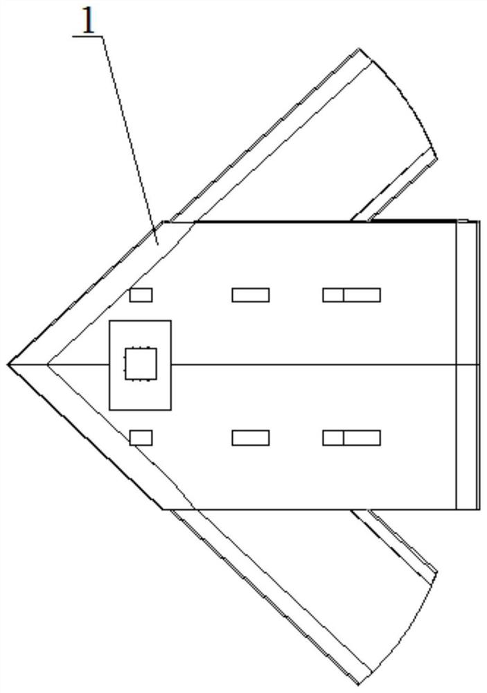
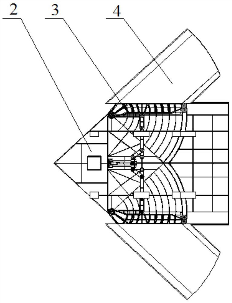
[0024] Specific implementation mode one: combine Figure 1 to Figure 9 Describe this embodiment, the telescopic wings of an aircraft based on the stroke amplification mechanism described in this embodiment include a drive unit and two sets of telescopic wing mechanisms, the two sets of telescopic wing mechanisms are arranged opposite to each other, and each set of telescopic wing mechanisms includes an inner wing cover Plate 1, inner wing 2, main rotary shaft 3, outer wing 4, transmission unit, locking unit and guide unit, inner wing cover plate 1 is installed on the upper end surface of inner wing 2, the front end of main rotary shaft 3 and inner wing The front end of 2 is rotationally connected, the outer wing 4 is arranged on the outside of the main rotary shaft 3, the drive unit controls the extension of the outer wing 4 along the guide unit to the outside of the inner wing 2 through the transmission unit, and the outer wing 4 is locked by the locking unit after unfolding i...
specific Embodiment approach 2
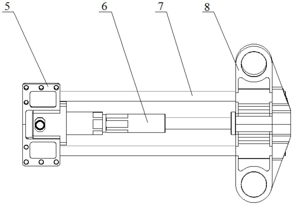
[0025] Specific implementation mode two: combination Figure 2 to Figure 3 Describe this embodiment, the drive unit described in this embodiment includes a support base 5, a fire working cylinder 6, a guide rod 7 and a slider 8, the support base 5 is fixed at the front end of the middle part between the two telescopic wing mechanisms, and the fire work The fixed end of the moving cylinder 6 is arranged on the support base 5, the guide rod 7 is arranged in the middle between the two telescopic wing mechanisms along the length direction, the movable end of the fire working cylinder 6 is slidingly connected with the guide rod 7, The movable end of 6 is connected with slide block 8 and connects. Other compositions and connection methods are the same as those in Embodiment 1.
[0026] In this embodiment, the pyrotechnic cylinder 6 is fixed by the support seat 5, and moves linearly on the guide rod 7, and drives the connected slider 8 to move.
[0027] The telescopic wing designed...
specific Embodiment approach 3
[0028] Specific implementation mode three: combination Figure 2 to Figure 4 Describe this embodiment, the two transmission units of this embodiment are symmetrically arranged on both sides of the slider 8, the transmission unit includes a crank 9, a rocker 10 and a connecting rod 11, one end of the crank 9 is rotationally connected with the slider 8, and the crank The other end of 9 is rotatably connected with the middle part of rocking bar 10, and one end of rocking bar 10 is rotatably connected with the inner side of inner wing 2, and the other end of rocking bar 10 is rotatably connected with one end of connecting rod 11, and the other end of connecting rod 11 is connected with main The middle part of the rotary shaft 3 is rotatably connected. Other compositions and connection methods are the same as those in the second embodiment.
[0029] In this embodiment, the expansion of the telescopic wings is driven by the pyrotechnic cylinder 6, which drives the slider 8 to move ...
PUM
 Abstract
Description
Claims
Application Information
 - R&D Engineer
- R&D Manager
- IP Professional
- Industry Leading Data Capabilities
- Powerful AI technology
- Patent DNA Extraction
Browse by: Latest US Patents, China's latest patents, Technical Efficacy Thesaurus, Application Domain, Technology Topic, Popular Technical Reports.
© 2024 PatSnap. All rights reserved.Legal|Privacy policy|Modern Slavery Act Transparency Statement|Sitemap|About US| Contact US: help@patsnap.com