Life buoy
A life buoy and a part of the technology, applied in the field of life buoys, can solve the problems of small radar corner reflectors with small reflection range, easy to miss when searching, easy to scratch people who fall into the water, etc., and achieve the effect of simple structure, good safety and scientific design
- Summary
- Abstract
- Description
- Claims
- Application Information
AI Technical Summary
Problems solved by technology
Method used
Image
Examples
Embodiment 1
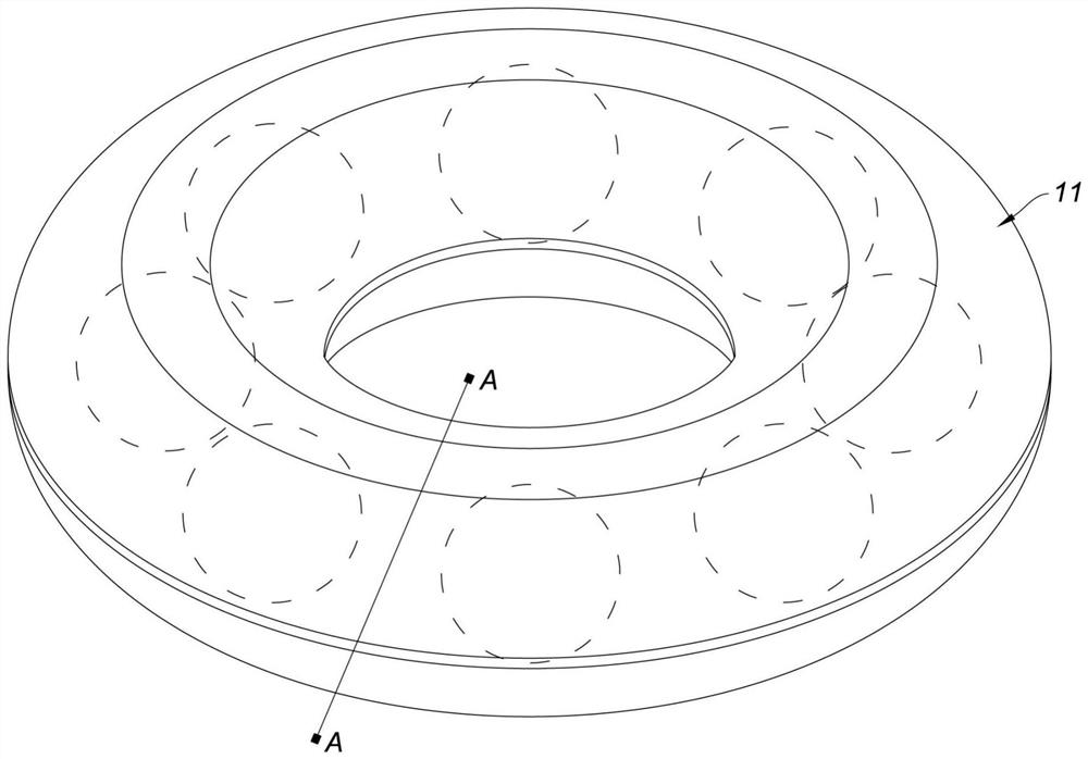
[0024] Such as figure 1 , figure 2 As shown, a kind of buoy buoy of the present embodiment comprises a buoy buoy body 11, and several radar reflectors are arranged in the buoy buoy body 11, and several radar reflectors are distributed in an annular array centered on the center of the buoy buoy body 11, and each radar The reflectors all include a Lunberg lens 12 and a reflector 13, the Lunberg lens 12 is made of a foam medium material, the reflector 13 is a thin metal sheet, and a reflective surface is formed on the reflector 13, the reflection of each radar reflector The reflective surface of the element 13 is attached to the surface of the Lunberg lens 12. The foamed dielectric material used to make the Lumber lens 12 is an existing material. The foamed dielectric material is just like the technology described in the patent No. 201910867980.8 titled "Dielectric Material and Dielectric Material Production Method" applied by the applicant. The scheme is the same, so it will ...
Embodiment 2
[0032] The difference between this embodiment and embodiment 1 is: as image 3 As shown, the diameter of the Luneberg lens 22 of each radar reflector 21 is larger than the cross-sectional diameter of the lifebuoy body, so that these radar reflectors 21 divide the lifebuoy body into several floating sections 23 . In the production process of this embodiment, the radar reflector 21 is integrally connected together when foaming to form the body of the life buoy. This design forms a recess between two adjacent radar reflectors 21. During use The underarm position of the person who fell into the water can clamp the concave position, which makes the life buoy more convenient to use.
Embodiment 3
[0034] The difference between this embodiment and Embodiment 1 lies in that: the reflection direction of the partial directional radar reflector and the reflection direction of the partial omnidirectional radar reflector are different. Specific as Figure 4 , Figure 5 As shown, there are two directional radar reflectors in Group A 31, which are respectively the first radar reflector 311 and the second radar reflector 312; there are also two directional radar reflectors in Group B 32, which are the first radar reflector 312 respectively; Three radar reflectors 321 and the fourth radar reflector 322; the first radar reflector 311, the second radar reflector 312, the third radar reflector 321 and the fourth radar reflector 322 are arranged in turn around the center of the buoy buoy body 33, Wherein: the central reflection direction L1 of the first radar reflector 311 and the central reflection direction L1 of the third radar reflector 321 are both perpendicular to the reference...
PUM
 Abstract
Description
Claims
Application Information
 - R&D
- Intellectual Property
- Life Sciences
- Materials
- Tech Scout
- Unparalleled Data Quality
- Higher Quality Content
- 60% Fewer Hallucinations
Browse by: Latest US Patents, China's latest patents, Technical Efficacy Thesaurus, Application Domain, Technology Topic, Popular Technical Reports.
© 2025 PatSnap. All rights reserved.Legal|Privacy policy|Modern Slavery Act Transparency Statement|Sitemap|About US| Contact US: help@patsnap.com


