
An integrated electrical module mounting bracket and its assembly

A mounting bracket and integrated technology, applied in the direction of transportation and packaging, circuits or fluid pipelines, vehicle components, etc., can solve the vibration requirements of the controller, can not meet the lightweight requirements of the whole vehicle, integrated installation in a bracket, etc. problems, to achieve good sealing and NVH performance, to solve the low maintenance efficiency, and to solve the effect of difficult installation

Active Publication Date: 2022-03-29
DONGFENG MOTOR CORP HUBEI
View PDF8 Cites 0 Cited by
  • Summary
  • Abstract
  • Description
  • Claims
  • Application Information

AI Technical Summary

Problems solved by technology

The invention patent with the authorized notification number CN104386005B provides a fixed structure for the automobile controller, which is connected by snap-fitting by setting the snap-on shrapnel on the box body of the controller and the snap-in points set on the upper bracket of the fixed structure. The controller is installed with the plug-in method. Compared with the traditional screwed or riveted fixed structure, this fixed structure is lighter in weight, and the installation is convenient and quick, but it is only suitable for assembling an electrical component of the controller, and does not connect the gateway and the control The controller and other electrical appliances are integrated and installed on a bracket, and it does not reflect how the structure meets the vibration requirements of the controller during driving, and the fixed structure adopts a sheet metal structure, which cannot meet the lightweight requirements of the whole vehicle

Method used


Image

  • An integrated electrical module mounting bracket and its assembly
  • An integrated electrical module mounting bracket and its assembly
  • An integrated electrical module mounting bracket and its assembly

Examples


Embodiment Construction

[0036] The present invention will be further described in detail below in conjunction with the accompanying drawings and specific embodiments to facilitate a clear understanding of the present invention, but they do not limit the invention. The positional relationships described in the embodiments are consistent with those shown in the accompanying drawings.

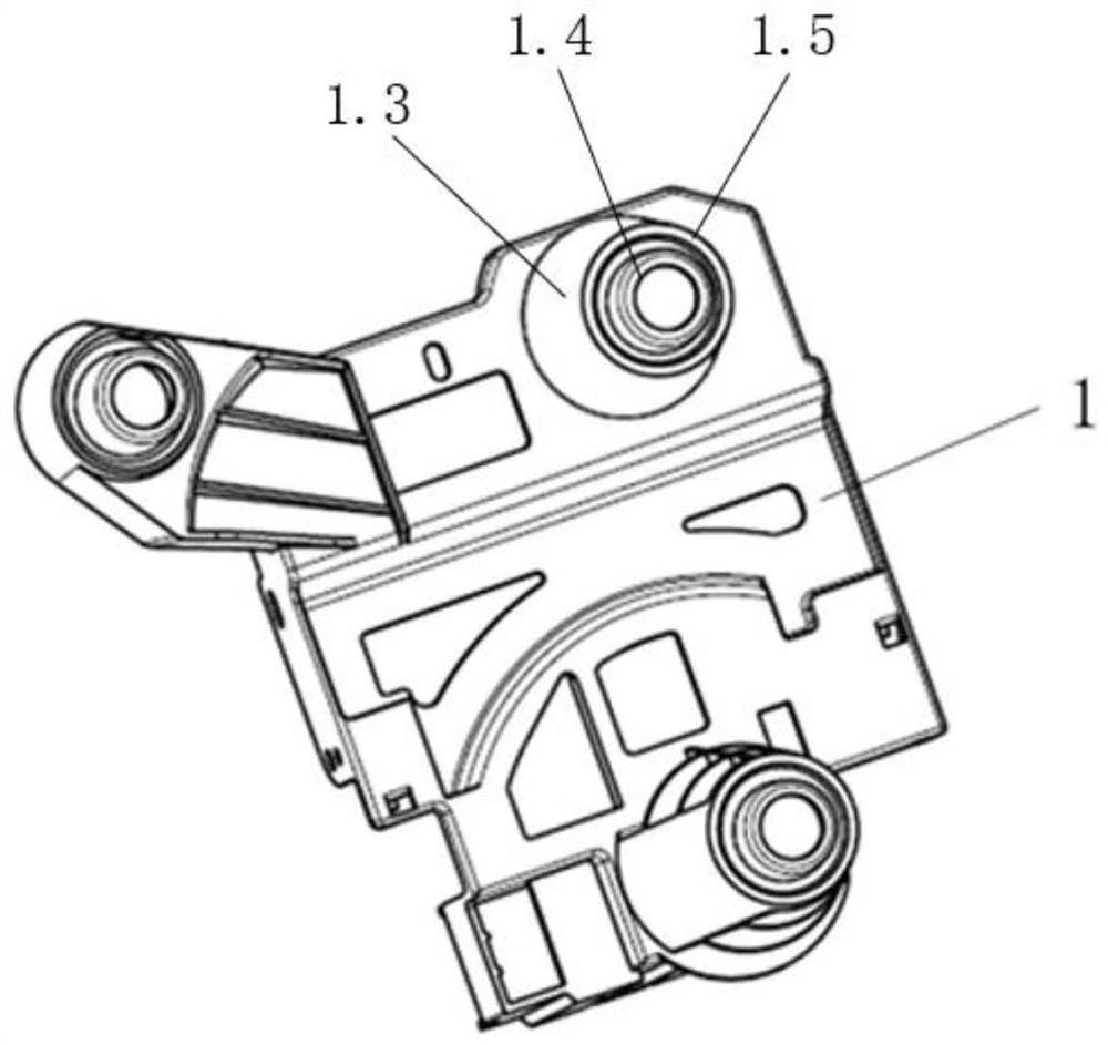
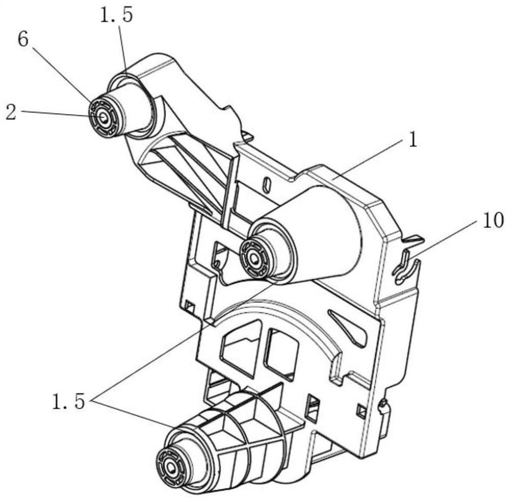
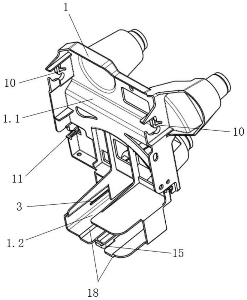
[0037] Such as figure 2 As shown, an integrated electrical module mounting bracket is composed of a mounting bracket body 1, a cushion cushion 6 and a plastic core 2. The structure and connection methods of each part of the mounting bracket will be described below.

[0038] Mounting bracket body 1 such as figure 1 As shown, one side of the mounting bracket body 1 is provided with three raised hollow columns 1.3, the upper end surface of the hollow column 1.3 is provided with an annular card interface 1.4, and the outer side of the hollow column 1.3 middle part is provided with a raised limiter 1.5. Cushion cushion 6 s...


PUM


Abstract

The invention provides an integrated electrical module mounting bracket and an assembly thereof. The mounting bracket includes a mounting bracket body, a buffer cushion and a plastic barrel core; the mounting assembly includes a mounting bracket and an electrical appliance. One side of the mounting bracket body of the present invention can simultaneously provide clamping or clamping and fixing installation parts for two electrical parts, and the outer side of the buffer cushion is clamped with the raised card interface on the other side of the mounting bracket body, and the cushioning soft The inner side of the pad is closely matched with the plastic core, and the mounting bracket and its assembly can be firmly installed on the front wall of the vehicle body through the plastic core. The present invention optimizes the layout space of the electrical appliance, the electrical appliance can be disassembled without tools, reduces the number of special parts, and lowers the cost; the installation method of the bracket and the damping chamber of the buffer cushion can effectively reduce vibration, ensuring the installation of the bracket and the electrical module. Reliable and durable; the bracket can be made of lightweight injection molded parts, and combined with its installation method, it has better airtightness and NVH performance than traditional sheet metal brackets.

Description

technical field [0001] The invention belongs to the field of automobile electrical module installation, and relates to an automobile body electrical module installation device and an assembly thereof. Background technique [0002] Some small electrical appliances of the car will be arranged inside the dashboard of the car. Generally, these small electrical appliances are fixed by relevant mounting brackets. These small electrical appliances such as Body Control Module (BCM) are one of the most important components in the car and are used to control common car functions that do not require a dedicated controller, including windows, mirrors, door locks and Functions such as car light control, and radio frequency receivers that receive information from car keys and tire pressure monitors; for example, car gateways are mainly used for data exchange and communication between different protocols and buses that belong to different electronic components on cars. Transmission conver...

Claims


Application Information

Patent Timeline
Patent Type & Authority Patents(China)
IPC IPC(8): B60R16/02
CPCB60R16/02
Inventor 邹星谢佳萍程康刘康宋瀚
Owner DONGFENG MOTOR CORP HUBEI
Learn More