Eureka AIR delivers breakthrough ideas for toughest innovation challenges, trusted by R&D personnel around the world.

Coated paper film laminating machine auxiliary equipment

A technology of auxiliary equipment and laminating machine, which is applied in the direction of special paper, lamination auxiliary operation, paper, etc., and can solve the problems of inability to process and cut accurate proofreading of coated paper

Pending Publication Date: 2021-02-26
华峰君
View PDF4 Cites 4 Cited by
  • Summary
  • Abstract
  • Description
  • Claims
  • Application Information

AI Technical Summary

Problems solved by technology

[0005] The purpose of the present invention is to provide an auxiliary equipment for a coated paper laminating machine to solve the problem that the processing and cutting of coated paper cannot be accurately checked and corrected in the above background technology

Method used


Image

  • Coated paper film laminating machine auxiliary equipment
  • Coated paper film laminating machine auxiliary equipment
  • Coated paper film laminating machine auxiliary equipment

Examples


Embodiment 1

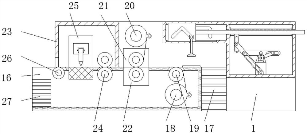
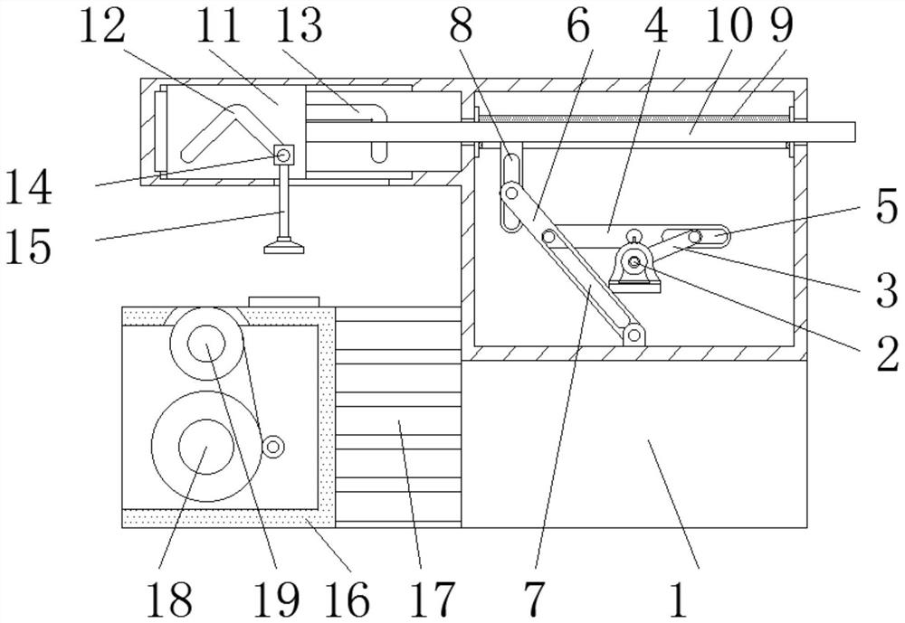
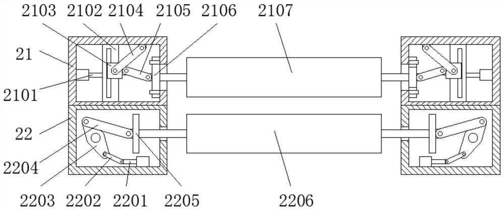
[0030] see Figure 1-7 , an auxiliary equipment for a coated paper laminating machine in an embodiment of the present invention, comprising a feeding frame 1, a motor 2 is fixedly installed on the inner wall of the feeding frame 1, and a first connecting rod 3 is screwed to the output end of the motor 2, The end of the first connecting rod 3 away from the motor 2 is screwed with the first rotating plate 4, and the connecting portion between the first rotating plate 4 and the first connecting rod 3 is provided with a first groove 5, and the first rotating plate 4 is far away from the first rotating plate 4. One end of the groove 5 is located at the inner wall of the feeding frame 1 and is screwed with a second rotating plate 6, and the connection part between the second rotating plate 6 and the first rotating plate 4 is provided with a second groove 7, and the second rotating plate 6 is away from One end of the second groove 7 is screwed with the first orifice 8, and the top ou...

Embodiment 2

[0032] Compared with Embodiment 1, in this embodiment, the third adjustment box 25 includes a third pneumatic push rod 2501, a third rotating plate 2502, a fifth groove 2503, a sixth connecting rod 2504, a fourth rotating plate 2505, The second orifice plate 2506, the second moving plate 2507 and the knife rest 2508, the inner wall of the third adjustment box 25 is fixedly connected with the third pneumatic push rod 2501, and the output end of the third pneumatic push rod 2501 is located at the third adjustment box 25 The inner wall is screwed with a third rotating plate 2502, and the connection between the third rotating plate 2502 and the third pneumatic push rod 2501 is provided with a fifth groove 2503, and the bottom of the fifth groove 2503 is screwed on the inner wall of the third rotating plate 2502. There is a sixth connecting rod 2504, and the end of the sixth connecting rod 2504 away from the third rotating plate 2502 is located on the inner wall of the third adjusti...


PUM


Abstract

The invention discloses coated paper film laminating machine auxiliary equipment which comprises a feeding frame, a motor is fixedly installed on the inner wall of the feeding frame, a first connecting rod is connected to the output end of the motor in a screwed mode, and a first rotating plate is connected to the end, away from the motor, of the first connecting rod in a screwed mode. In the coated paper film laminating machine auxiliary equipment, through arrangement of the moving plate, in the feeding frame, a motor rotates to drive a first connecting rod to rotate, the first connecting roddrives a first rotating plate to rotate through a first groove, the first rotating plate drives a second rotating plate to rotate through a second groove, the rotating angle of the second rotating plate is 120 degrees, and the second rotating plate drives a telescopic rod to slide in a telescopic cylinder barrel through a first pore plate; then the sliding length of the telescopic rod is equal tothe horizontal length of the fourth groove, the telescopic rod drives the movable plate to move, the movable plate drives the movable block to slide along the fourth groove through the third groove,wherein the third groove is in an inverted V shape and the fourth groove is in a U shape; the movable block drives the suction cup to move, and automatic feeding operation of coated paper is achieved.

Description

technical field [0001] The invention relates to the technical field of coated paper laminating machines, in particular to auxiliary equipment for coated paper laminating machines. Background technique [0002] Coated paper, also known as printing coated paper, is coated with a layer of white paint on the surface of base paper and processed by super calendering. It is divided into two types: single-sided and double-sided, and the paper surface is divided into two types: glossy surface and cloth texture. High density, good ink absorption performance, mainly used for offset printing, gravure fine screen printing, such as high-end picture albums, calendars, books, etc. The disadvantage is that the powder is easy to stick and fall off after being wet, and cannot be stored for a long time. [0003] When the coated paper is processed, the coated paper laminating machine will be used. The coated paper laminating machine needs some auxiliary equipment to proofread the coated paper. T...

Claims


Application Information

Patent Timeline
Patent Type & Authority Applications(China)
IPC IPC(8): B32B37/10B32B38/00B32B38/18D21H27/30
CPCB32B37/10B32B38/0004B32B38/1833B32B38/1858D21H27/30
Inventor 华峰君
Owner 华峰君
Why Eureka
Eureka Blog
Learn More