Civil engineering stone sand screening device

A screening device and stone sand technology, which is applied in the direction of filter screen, solid separation, grille, etc., can solve the problems of affecting the screening effect, stone sand agglomeration due to moisture, etc., and achieve the goal of ensuring the screening effect, flexible and convenient use, and reasonable structural design Effect

Active Publication Date: 2021-02-26
山东电子职业技术学院
View PDF11 Cites 0 Cited by
  • Summary
  • Abstract
  • Description
  • Claims
  • Application Information

AI Technical Summary

Problems solved by technology

[0005] The present invention provides a civil stone sand screening device, which is used to solve the problem that the stone sand is damp and agglomerated and affects the screening effect, so as to break the stone sand agglomeration phenomenon and improve Beneficial Effects of Screening Effects

Method used


Image

  • Civil engineering stone sand screening device
  • Civil engineering stone sand screening device
  • Civil engineering stone sand screening device

Examples


Embodiment 1

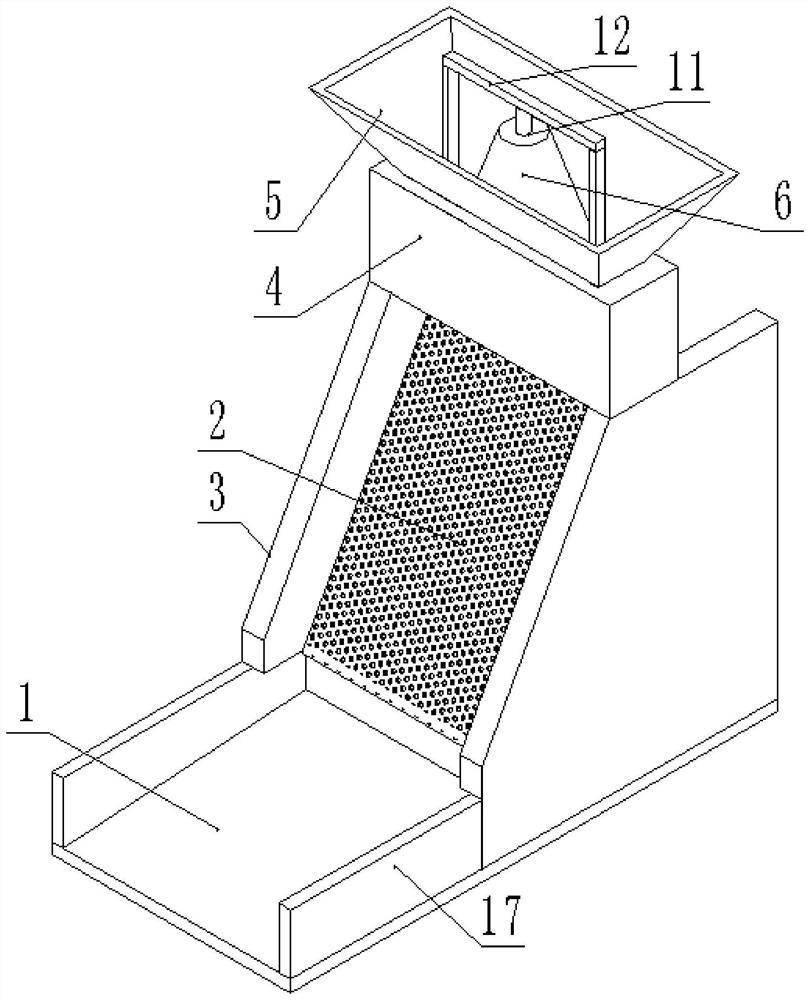
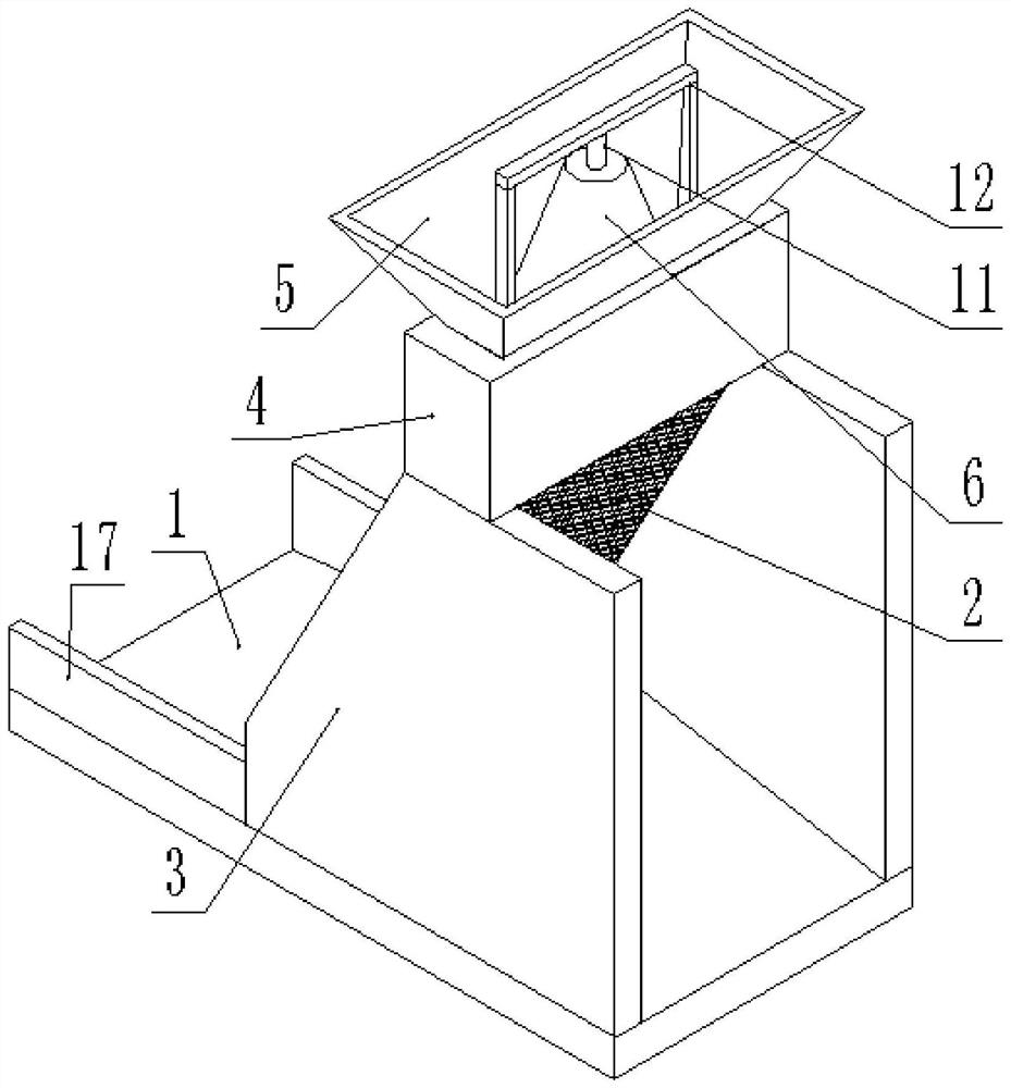
[0032] A civil stone sand screening device, such as figure 1 and figure 2 As shown, it includes a base 1 and a sand net 2, the base 1 is provided with a mounting plate 3, and an inclined sand net 2 is arranged between the mounting plates 3; the outside of the base 1 is provided with a fence 17, and one side of the base 1 A gap is provided, and the base 1 is respectively provided with slopes on both sides of the sand net 2 .

[0033] After the sand net 2 screens the stones and sand, the stones and sand are separated and fall to the base 1 respectively and leave along the slope on the base to prevent accumulation at the connection between the sand net 2 and the base 1 and affect the subsequent screening effect; And the mounting plate 3 and the fence 17 can limit the scope of falling stones and sand, prevent the stones and sand from being scattered randomly after screening and cause unnecessary cleaning work.

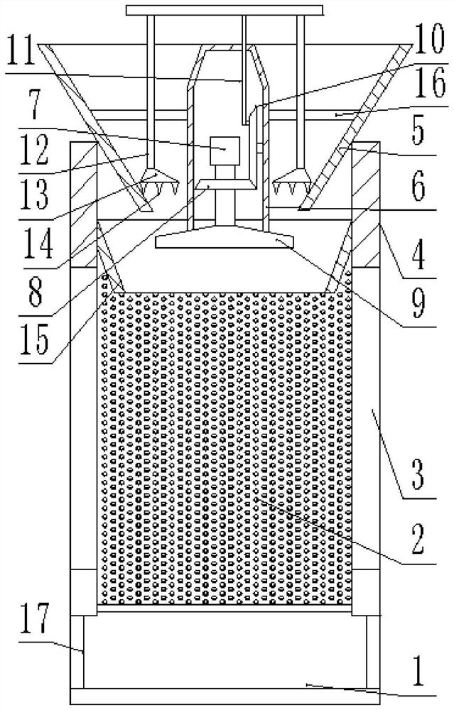
[0034] Such as figure 1 and image 3 As shown, the upper side of...

Embodiment 2

[0041] On the basis of Example 1, such as Figure 4 As shown, the inside of the mounting plate 3 is respectively provided with a cylinder 18 with a notch, and the cylinder 18 is provided with a rotating shaft 19 on which a sand net 2 passing through the gap is installed, and the sand net 2 is wound on the rotating shaft 19 . The sand net 2 is an orderly combination of multiple sand nets 2 with different specifications. By rotating the rotating shaft 19, the sand net 2 is wound on its outside, so as to change the use specifications of the sand net 2 and meet more usage scenarios.

[0042] Such as Figure 4 As shown, one end of the rotating shaft 19 is provided with a ratchet 21 and a ratchet 22, and one end of the ratchet 22 is obliquely installed with a resettable knocking rod 23, and the knocking rod 23 is positioned at one side of the sand net 2; , the rotating shaft 19 drives the ratchet 21 to rotate all the time, and the ratchet 21 rotates so that the ratchet 22 drives th...


PUM


Abstract

The invention provides a civil engineering stone sand screening device. The civil engineering stone sand screening device comprises a base and a sand net, wherein mounting plates are arranged on the base, and the inclined sand net is arranged between the mounting plates; a shell with an upper opening and a lower opening is arranged on the upper sides of the mounting plates, a hopper is arranged onone side in the shell, an inner sleeve connected with the hopper is arranged in the hopper, a motor is arranged on the lower side of the inner sleeve, a driving wheel is arranged at one end of an output shaft of the motor, a material receiving disc with a slope is arranged on one side of the driving wheel, a driven wheel matched with the driving wheel is arranged on one side of a motor shell, a connecting rod is arranged on one side of the driven wheel, the connecting rod penetrates through the upper side of the inner sleeve, and a material smashing rod is arranged at one end of the connecting rod and is located between the hopper and the inner sleeve.

Description

technical field [0001] The invention belongs to the technical field of civil construction stone sand screening equipment, in particular to a civil construction stone sand screening device. Background technique [0002] Most of the civil engineering mentioned today generally refers to minor civil engineering, including the primary construction of residences, public buildings, structures, etc. Such as precipitation, earth excavation, foundation laying, pouring of columns, beams, slabs and walls and other maintenance structure pouring and masonry projects and supporting steel bars, simple decorations, etc. In the field of civil engineering, when using raw materials such as stone and sand, it is often necessary Manual screening is very inefficient and time-consuming. [0003] Since the stone sand will be agglomerated when it is wet or in contact with water, it will not be able to effectively screen when it is in contact with the sand net; for the agglomerated stone sand, it wil...

Claims


Application Information

Patent Timeline
Patent Type & Authority Applications(China)
IPC IPC(8): B07B1/46B07B1/54B02C19/00
CPCB07B1/46B07B1/4609B07B1/54B02C19/0018
Inventor 许红蕾刘文臣李军刘倩倩
Owner 山东电子职业技术学院
Why Eureka
Try Eureka