Eureka AIR delivers breakthrough ideas for toughest innovation challenges, trusted by R&D personnel around the world.

Vehicle synchronizer assembly and vehicle

A synchronizer and vehicle technology, which is applied to the transmission field of vehicles, can solve the problems of incomplete meshing, wear of gear sleeves and engaging teeth, etc., and achieves the effect of avoiding wear and tearing.

Active Publication Date: 2021-02-23
ZHEJIANG GEELY HLDG GRP CO LTD +4
View PDF7 Cites 0 Cited by
  • Summary
  • Abstract
  • Description
  • Claims
  • Application Information

AI Technical Summary

Problems solved by technology

[0005] An object of the present invention is to solve the technical problem of incomplete meshing after shifting due to the wear of the locking angle between the gear sleeve and the engaging teeth in the synchronizer

Method used


Image

  • Vehicle synchronizer assembly and vehicle
  • Vehicle synchronizer assembly and vehicle

Examples


Embodiment Construction

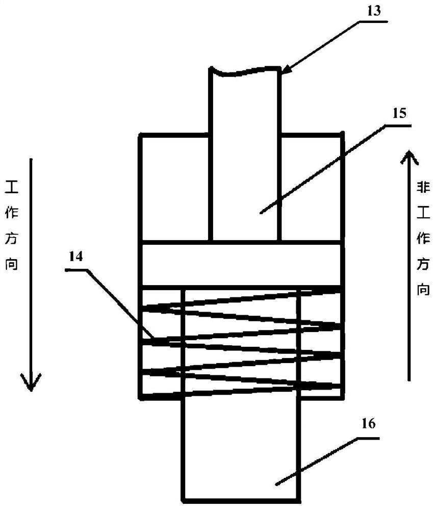
[0029] figure 1 A schematic structural diagram of a vehicle synchronizer assembly according to an embodiment of the present invention is shown. like figure 1 As shown, the vehicle synchronizer assembly generally includes a gear hub 6 , a gear sleeve 7 , a slider 5 , a synchronization ring 2 , engaging teeth, a spring 3 and a steel ball 4 . The gear hub 6 is sleeved outside the working shaft of the vehicle, and the gear sleeve 7 is sleeved outside the gear hub 6 . The gear sleeve 7 is driven by the shift fork to move axially, passes through the synchronous ring 2, and meshes with the gear gear 11 to realize shifting and transmitting torque. The synchronous ring 2 synchronizes the speed gear 11 and the gear sleeve 7 with different rotating speeds quickly before engaging the teeth through the conical surface friction pair. In order to solve the technical problem of incomplete meshing after shifting due to wear of the locking angle between the tooth sleeve 7 and the engaging to...


PUM


Abstract

The invention provides a vehicle synchronizer assembly and a vehicle. The vehicle synchronizer assembly comprises a gear hub sleeving a working shaft of a vehicle, a gear sleeve sleeving the gear huband at least one hydraulic rod device arranged in the circumferential direction of a shifting fork groove of the gear sleeve and spaced from the shifting fork groove. Each hydraulic rod device comprises a hydraulic rod and a driving mechanism for driving the hydraulic rods to reciprocate between a working state of being clamped in the shifting fork groove and a non-working state of exiting from the shifting fork groove. The driving mechanisms are configured to drive the hydraulic rods to be in the working state to prevent the gear sleeve from being connected with the gear-position gear when the rotating speed of the working shaft is different from the rotating speed of the gear-position gear to be connected with the gear sleeve, and when the rotating speed of the working shaft is the sameas that of the gear-position gear, the hydraulic rods are driven to be in the non-working state to enable the gear sleeve to be connected with the gear-position gear. According to the scheme of the vehicle synchronizer assembly, the technical problem of incomplete meshing after gear engagement due to the fact that the locking angles of the gear sleeve and joint gears are abraded is solved.

Description

technical field [0001] The invention relates to the technical field of vehicle transmissions, in particular to a vehicle synchronizer assembly and a vehicle. Background technique [0002] As an important part of automobile products, the transmission can ensure the best working condition of the engine and realize the reverse gear of the automobile. Synchronizers are key components for gear shifting in automotive transmissions, including sub-components such as gear hubs, gear sleeves, sliders, synchronization rings, and engaging teeth. The gear sleeve is driven by the shift fork to move axially, passes through the synchronous ring, and meshes with the engaging teeth to realize shifting and transmission of torque. The synchronous ring synchronizes the gears with different speeds and the tooth sleeves quickly before engaging the teeth through the conical surface friction pair. [0003] The vehicle gear shift of MT / AMT / DCT is realized through the clutch. The clutch is separate...

Claims


Application Information

Patent Timeline
IPC IPC(8): F16D23/02F16H63/40F16H61/18G01P3/00
CPCF16D23/02F16H63/40F16H61/18G01P3/00
Inventor 王翔谭艳军林霄喆王瑞平安聪慧肖逸阁
Owner ZHEJIANG GEELY HLDG GRP CO LTD
Why Eureka
Eureka Blog
Learn More