Wringing machine with flow guide mechanism

A technology of diversion mechanism and water squeezer, which is applied in raw hide/leather/fur manufacturing equipment, small raw hide/large raw hide/leather/fur mechanical treatment, small raw hide/large raw hide/leather/fur treatment, etc., which can solve the inconvenience Manage and manufacture complex structures, inconvenient large-scale production and manufacturing, etc., to achieve the effect of easy management and simple structure

Inactive Publication Date: 2021-02-23
陈家其
View PDF6 Cites 0 Cited by
  • Summary
  • Abstract
  • Description
  • Claims
  • Application Information

AI Technical Summary

Problems solved by technology

[0004] The purpose of the present invention is to solve the complex manufacturing structure of the water squeezer in the prior art, the high production cost, and the high price of the water squeezer at the same time, which is not convenient for large-scale production. At the same time, the existing water squeezer has no The diversion mechanism of the water flow causes the extruded water to spill on the ground, which is not easy to take care of, and a water squeezer with a diversion mechanism is proposed

Method used


Image

  • Wringing machine with flow guide mechanism
  • Wringing machine with flow guide mechanism
  • Wringing machine with flow guide mechanism

Examples


Embodiment 1

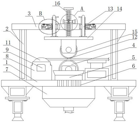
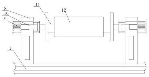
[0026] refer to Figure 1-5 , a water squeezing machine with a diversion mechanism, including a fixed frame 1, two symmetrically arranged support plates 2 are fixedly installed on the top of the fixed frame 1, and the same top plate 3 is fixedly installed on the top of the two support plates 2, The top of the fixed frame 1 is fixedly equipped with a flow guide tube 5, and the top of the fixed frame 1 is fixedly equipped with a lower drum 4, and the lower drum 4 is located in the flow guide tube 5, and the fixed frame 1 is provided with a plurality of flow guide holes 6. Each diversion hole 6 is positioned directly below the diversion pipe 5, and the bottom of the fixed frame 1 is fixedly equipped with a water tank 7, and a plurality of diversion holes 6 are all connected with the water tank 7, and the top of the fixed frame 1 is fixedly installed. There are two mounting bases 8 arranged symmetrically, and the same storage roller 11 is rotatably connected to the two mounting ba...

Embodiment 2

[0035] refer to Figure 1-5 , a water squeezing machine with a diversion mechanism, including a fixed frame 1, two symmetrically arranged support plates 2 are fixedly installed on the top of the fixed frame 1, and the same top plate 3 is fixedly installed on the top of the two support plates 2, The top of the fixed frame 1 is fixedly equipped with a flow guide tube 5, and the top of the fixed frame 1 is fixedly equipped with a lower drum 4, and the lower drum 4 is located in the flow guide tube 5, and the fixed frame 1 is provided with a plurality of flow guide holes 6. Each diversion hole 6 is positioned directly below the diversion pipe 5, and the bottom of the fixed frame 1 is fixedly equipped with a water tank 7, and a plurality of diversion holes 6 are all connected with the water tank 7, and the top of the fixed frame 1 is fixedly installed. There are two mounting bases 8 arranged symmetrically, and the same storage roller 11 is rotatably connected to the two mounting ba...


PUM


Abstract

The invention belongs to the technical field of wringing machines, and particularly relates to a wringing machine with a flow guide mechanism. Aiming at the problems that an existing wringing machineis complex in manufacturing structure and high in production cost, and meanwhile, the wringing machine is not provided with a flow guide mechanism for water flow, so that extruded water is scattered on the ground, the scheme is proposed as follows. The wringing machine comprises a fixing frame, wherein two symmetrically-arranged supporting plates are fixedly installed at the top of the fixing frame, the same top plate is fixedly installed at the tops of the two supporting plates, a flow guide pipe is fixedly installed at the top of the fixing frame, a lower roller is fixedly installed at the top of the fixing frame, and the lower roller is located in the flow guide pipe. The wringing machine is simple in structure, one end of leather is fixed to the outer side of a storage roller, then theheight of an upper roller is adjusted so that the leather can be wrung, squeezed water can flow into a water containing tank through the flow guide pipe, therefore the squeezed water cannot be scattered on the ground, and great convenience is brought to workers to take care of the leather.

Description

technical field [0001] The invention relates to the technical field of water squeezers, in particular to a water squeezer equipped with a flow guiding mechanism. Background technique [0002] The existence of leather and related industries has a long history and tradition in our country. Like other national industries, it has also experienced the transformation from backward workshop-style individual processing to cluster production and modern scale production in terms of form and scale of business activities. Especially since the mid-1980s, with the large-scale transfer of the leather industry from developed countries and regions such as Italy, Spain, Taiwan, and Hong Kong to developing countries, it has triggered a rapid influx of advanced technology, talents, chemicals and equipment. my country, which was backward in the processing of leather and leather products, has rapidly developed into an international "leather power". However, due to the relatively weak foundation of ...

Claims


Application Information

Patent Timeline
Patent Type & Authority Applications(China)
IPC IPC(8): C14B1/02C14B17/04C14B17/14
CPCC14B1/02C14B17/04C14B17/14
Inventor 陈家其
Owner 陈家其
Why Eureka
Try Eureka