
Automatic taking device for stand column parts

A technology for automatic reclaiming of materials and parts, applied in auxiliary devices, transportation and packaging, conveyor objects, etc., can solve problems such as low efficiency, and achieve the effect of improving efficiency, ensuring placement accuracy, and improving welding accuracy.

Pending Publication Date: 2021-02-23
WUCHUAN HEAVY ENG +1
View PDF6 Cites 1 Cited by
  • Summary
  • Abstract
  • Description
  • Claims
  • Application Information

AI Technical Summary

Problems solved by technology

[0003] In view of this, the purpose of the present invention is to overcome the deficiencies of the prior art and provide an automatic pick-up device for column parts to solve the technical problem of low efficiency in the prior art of manual handling of column parts

Method used


Image

  • Automatic taking device for stand column parts
  • Automatic taking device for stand column parts
  • Automatic taking device for stand column parts

Examples


Embodiment 1

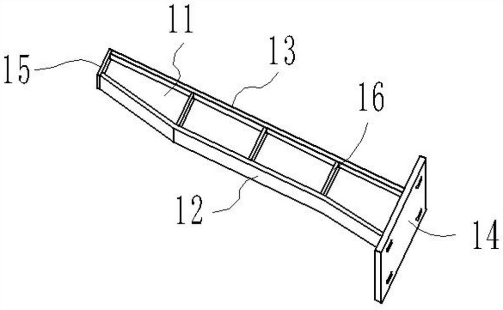
[0029] The structure of the column formed after welding the column components in this embodiment is as follows: figure 1 As shown, the first vertical plate 12 and the second vertical plate 13 are spaced apart, and one end of the first vertical plate 12 and one end of the second vertical plate 13 are welded to the bottom plate 14, and the other end of the first vertical plate 12 is connected to the second vertical plate 14. The other end of the plate 13 is welded with the top plate 15, and the partition plate 11 is welded and fixed in the frame-shaped structure formed by the welding of the first vertical plate 12, the bottom plate 14, the second vertical plate 13 and the top plate 15 in turn, and the partition plate 11 is welded. Rib plates 16 are welded symmetrically on both sides, and two ends of the rib plate 16 are connected with the first vertical plate 12 and the second vertical plate 13 .

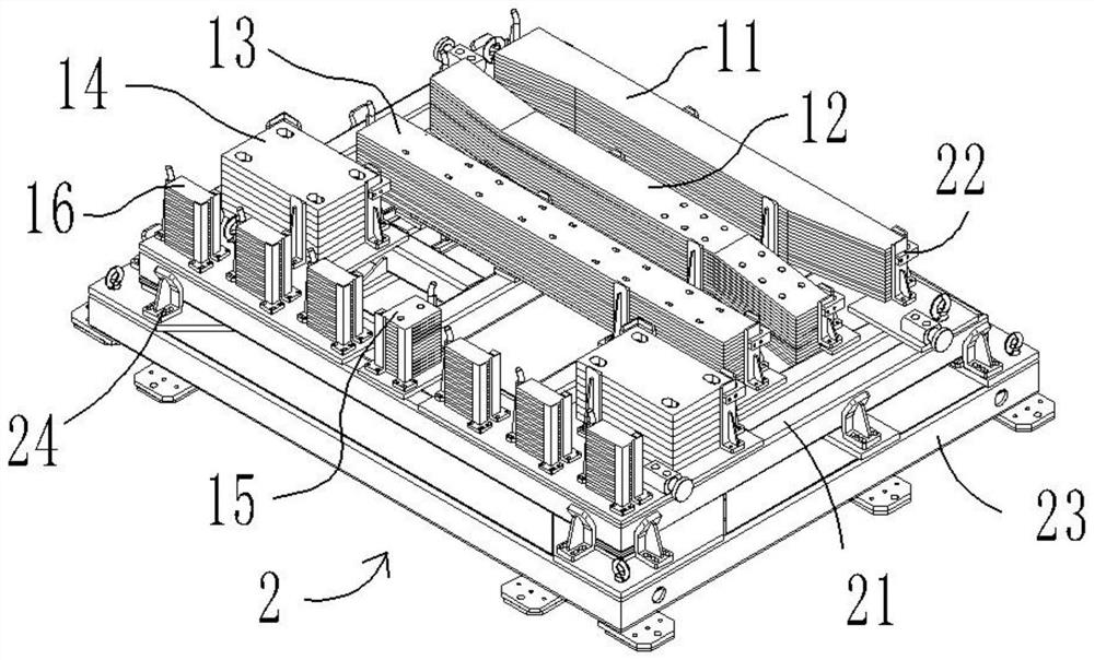
[0030] like figure 2 As mentioned above, an automatic identification device for...


PUM


Abstract

The invention relates to an automatic taking device for stand column parts, and belongs to the technical field of stand column welding. An automatic clamping device comprises a material frame and a carrying robot, a bottom plate, a top plate, a first vertical plate, a second vertical plate, a partition plate and a rib plate are placed on the upper area of the material frame, the carrying robot comprises a mechanical arm and a plurality of adsorption devices connected to the mechanical arm, and each adsorption device is used for adsorbing one or more parts. The carrying robot carries the partsinto a welding clamp one by one through the adsorption devices to be fixed. Therefore, existing manual carrying is replaced, the carrying efficiency is improved, meanwhile, the placing precision of all the stand column parts in the welding clamp can be guaranteed, and the welding precision of stand columns can be improved.

Description

technical field [0001] The invention belongs to the technical field of column welding, and particularly relates to an automatic reclaiming device for column components. Background technique [0002] The central column of the bridge accessory component is a common part of the steel bridge or concrete bridge deck, and its number is large, and the specifications and structural forms are relatively simple. At present, the storage frame only has an independent storage function, and cannot be stored in the storage frame according to the needs of component production. The parts are automatically identified and picked up. At present, for such components, simple tooling is mainly used. After the parts are blanked, they must be accurately scribed, and the corresponding parts are manually assembled according to the positioning lines, which has low work efficiency. The platform and tooling only fulfill the function of limiting the shape of the parts, and cannot achieve the accurate del...

Claims


Application Information

Patent Timeline
IPC IPC(8): B23K37/00B25J15/00B25J15/06B65G47/92
CPCB23K37/00B25J15/00B25J15/0608B65G47/92
Inventor 郭萍萍阮家顺饶嵩杨帆
Owner WUCHUAN HEAVY ENG
Learn More