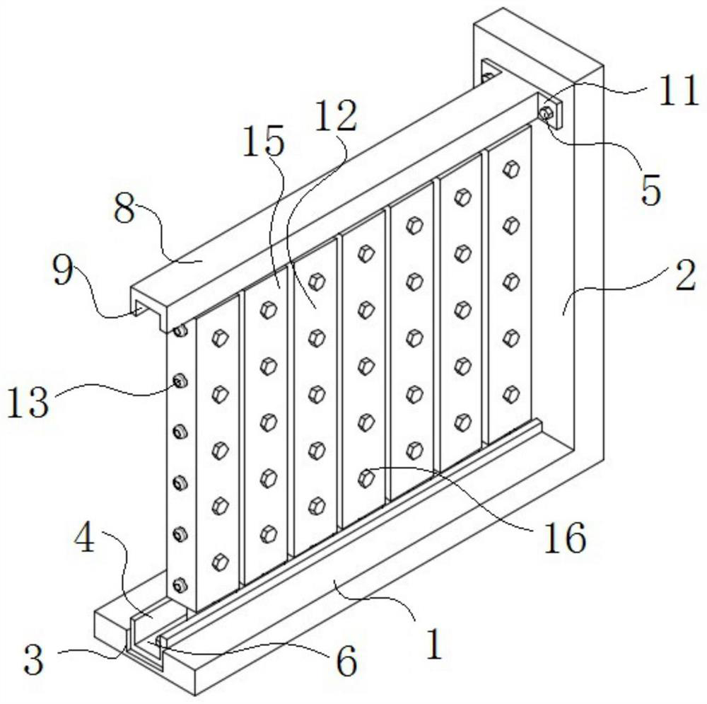
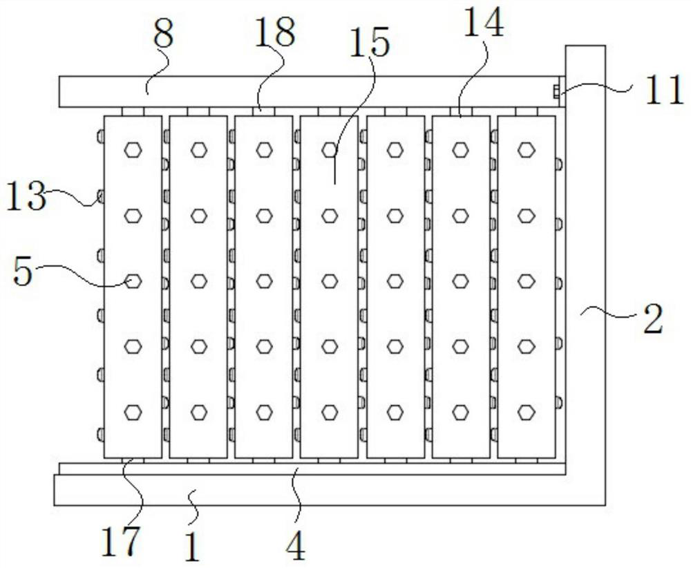
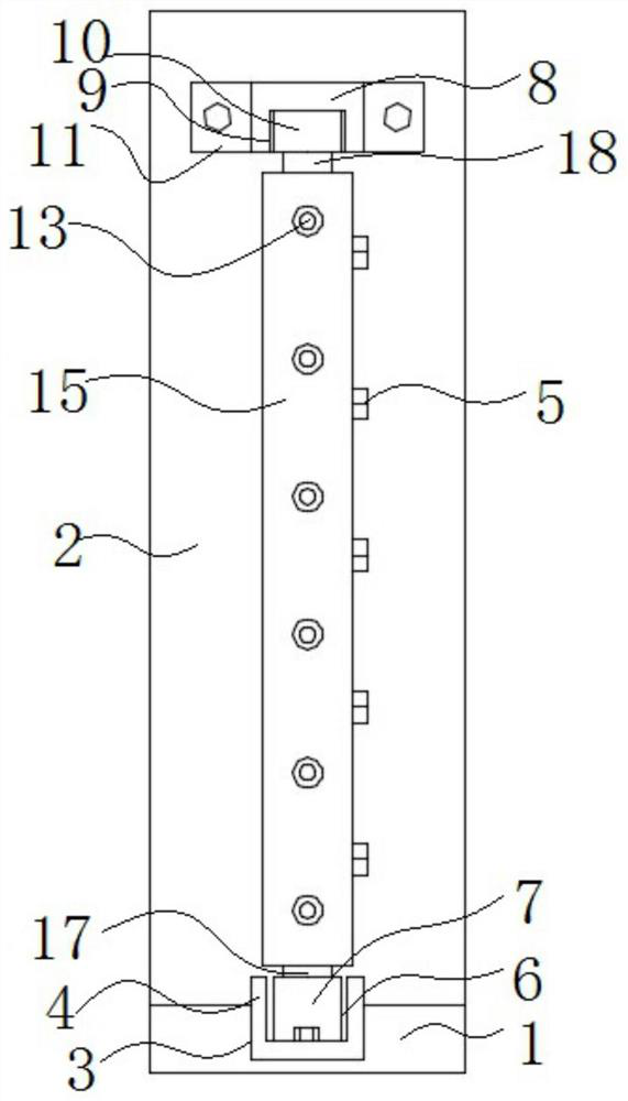
Fabricated steel structure house module connecting structure for building decoration

A technology for building modules and connecting structures, applied in building structures, buildings, floors, etc., can solve the problems of difficult air circulation, poor air circulation, and long installation period, so as to maintain air quality, reduce installation period, and save time. Effect

Pending Publication Date: 2021-02-19
GOLD MANTIS FINE DECORATION TECH SUZHOU CO LTD
View PDF0 Cites 1 Cited by
  • Summary
  • Abstract
  • Description
  • Claims
  • Application Information

AI Technical Summary

Problems solved by technology

[0005] Aiming at the problem that the existing building module connection structure only has a single connection and fixing structure, which completely separates the room from the room, makes it difficult for indoor air circulation, and the installation is complicated, the installation period is long, and time-consuming and laborious. The purpose of the present invention is to provide A prefabricated steel structure house module connection structure for building decoration, through the structure of the base, the top and the fixing bolts, it is convenient for the installation and disassembly of the structure, reducing the installation cycle and saving time, and it is convenient for supporting through the structure of several rotating seats and several rotating joints The rotation of the columns facilitates the air circulation between the houses and maintains the air quality of the houses. Through the clamping structure, it is convenient for the two support columns to be fixed to each other and maintain their stability, which solves the existing problems of poor air circulation, long installation period and time-consuming strenuous problem

Method used


Image

  • Fabricated steel structure house module connecting structure for building decoration
  • Fabricated steel structure house module connecting structure for building decoration
  • Fabricated steel structure house module connecting structure for building decoration

Examples


Embodiment Construction

[0029] Embodiments of the present invention are described in detail below, examples of which are shown in the drawings, wherein the same or similar reference numerals denote the same or similar elements or elements having the same or similar functions throughout. The embodiments described below by referring to the figures are exemplary only for explaining the present invention and should not be construed as limiting the present invention.

[0030] In describing the present invention, it should be understood that the terms "upper", "lower", "vertical", "horizontal", "top", "bottom", "inner", "outer" and the like indicate an orientation or The positional relationship is based on the orientation or positional relationship shown in the drawings, which is only for the convenience of describing the present invention and simplifying the description, rather than indicating or implying that the referred device or element must have a specific orientation, be constructed and operated in a...


PUM


Abstract

The invention discloses a fabricated steel structure house module connecting structure for building decoration, and relates to the technical field of house building decoration. The structure comprisesa floor, a wall body, a base, a supporting structure and clamping and fixing structures, wherein a first mounting groove is formed in the upper surface of the floor, the base is mounted in the firstmounting groove, the supporting structure is mounted on the upper surface of the base, a top seat is mounted at one end of the supporting structure, one end of the top seat is connected with the wallbody, and the clamping and fixing structures are arranged on two opposite surfaces of the supporting structure. According to the structure, through the structure of the base, the top seat and fixing bolts, the structure is convenient to mount and dismount, the mounting period is shortened, time is saved, through the structures of multiple rotating seats and multiple rotating joints, rotation of supporting columns is facilitated, air circulation between houses is facilitated, the air quality of the houses is kept, and through the clamping and fixing structures, mutual fixing between the two supporting columns is facilitated, and the stability is maintained.

Description

technical field [0001] The invention belongs to the technical field of building decoration, in particular to an assembled steel structure building module connection structure for building decoration. Background technique [0002] Prefabricated building refers to the transfer of a large number of on-site operations in the traditional construction method to the factory, where the building components and accessories (such as floor slabs, wall panels, stairs, balconies, etc.) are processed and manufactured in the factory, and transported to the construction site. Reliable connection methods are assembled and installed on site. Prefabricated buildings mainly include prefabricated concrete structures, steel structures, modern wooden structures, etc., because standardized design, factory production, assembly construction, information management, Intelligent application is the representative of modern industrial production mode. With the development of modern industrial technology, ...

Claims


Application Information

Patent Timeline
Patent Type & Authority Applications(China)
IPC IPC(8): E04B1/38E04F15/02E04B1/343
CPCE04B1/38E04F15/02E04B1/343E04B1/388
Inventor 陆晓朋周丰昌崔武于会影袁胜谢亚恒张梦祥杨婷婷
Owner GOLD MANTIS FINE DECORATION TECH SUZHOU CO LTD
Why Eureka
Try Eureka