
Metal surface highlight drilling and cutting device

A metal surface, drilling and cutting technology, used in metal processing equipment, metal processing, manufacturing tools, etc., can solve problems such as debris splashing and poor protection effect

Pending Publication Date: 2021-02-19
上海皓腾模型有限公司
View PDF1 Cites 0 Cited by
  • Summary
  • Abstract
  • Description
  • Claims
  • Application Information

AI Technical Summary

Problems solved by technology

[0004] However, the drill bit and milling cutter of the above-mentioned automatic drilling and cutting equipment for metal surfaces are always exposed. Even if there is a filter screen to block, debris may splash out from the gap between the filter screens, so the protection effect is poor.

Method used


Image

  • Metal surface highlight drilling and cutting device
  • Metal surface highlight drilling and cutting device
  • Metal surface highlight drilling and cutting device

Examples


Embodiment

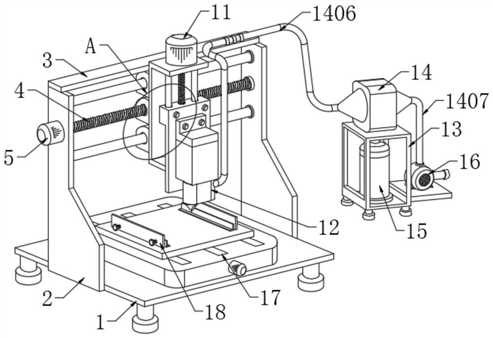
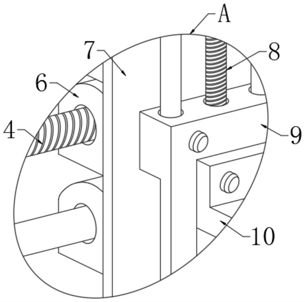
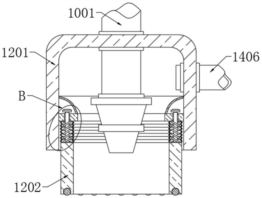
[0030] refer to Figure 1-6 In this embodiment, a metal surface highlight drilling and cutting equipment is proposed, including a base 1, two vertical plates 2 are fixedly installed on the top of the base 1, and the same horizontal plate 3 is fixedly installed on the top of the two vertical plates 2, and the two The same first screw rod 4 is rotatably installed on two risers 2, and a first motor 5 is fixedly installed on one side of one riser 2, and one end of the first screw rod 4 close to the first motor 5 passes through the corresponding riser 2 and is connected with the first riser 2. The output shafts of the first motor 5 are fixedly connected together, the first screw rod 4 is threaded with a first rectangular column 6, the first rectangular column 6 is fixedly mounted with a mounting frame 7, and the mounting frame 7 is rotatably mounted with a second screw rod 8. The second screw rod 8 is provided with a fixed plate 9 on the threaded sleeve. The second motor 10 is fixe...


PUM


Abstract

The invention belongs to the technical field of drilling and cutting devices, and particularly relates to a metal surface highlight drilling and cutting device. The metal surface highlight drilling and cutting device comprises a base, wherein two vertical plates are fixedly installed at the top of the base; the same transverse plate is fixedly installed at the top ends of the two vertical plates;the same first screw rod is rotationally installed on the two vertical plates; a first motor is fixedly installed on one side of one vertical plate; the end, close to the first motor, of the first screw rod penetrates through the corresponding vertical plate and is fixedly connected with an output shaft of the first motor; the first screw rod is sleeved with a first rectangular column in a threaded mode; a mounting frame is fixedly installed on the first rectangular column; a second screw rod is rotationally installed on the mounting frame; and the second screw rod is sleeved with a fixing disc in a threaded mode. According to the metal surface highlight drilling and cutting device, a drill bit and a milling cutter can be prevented from being exposed outside, so that all metal chippings can be blocked and discharged when a metal workpiece is machined, the situation that the metal chippings splash is avoided, and the advantages of being good in protection effect, high in safety and thelike are achieved.

Description

technical field [0001] The invention relates to the technical field of drilling and cutting equipment, in particular to a high-gloss drilling and cutting equipment for metal surfaces. Background technique [0002] With the continuous development of the times, the machining industry continues to develop and grow, and the existing processing slowly develops from manual operation to machine automation. [0003] After retrieval, the authorization announcement number CN208601021U discloses an automatic drilling and cutting equipment for metal surfaces. It is proposed that the drilling and cutting processes for processing metal surfaces are generally carried out separately, and the problem of wasting time and splashing waste chips easily affects the normal work of the staff. Afterwards, the waste chips generated during the drilling and cutting process can be collected through the provided filter screen, so as to prevent the waste chips from splashing and affecting the drilling and...

Claims


Application Information

Patent Timeline
IPC IPC(8): B23Q37/00
CPCB23Q37/002
Inventor 冯纯钢
Owner 上海皓腾模型有限公司
Learn More