3D rotary spray water outlet device
A technology for a water outlet and water splash, which is applied in the direction of a spray device, a spray device, a spray device and the like with a movable outlet, can solve the problems of a large space, the shape of the water spray is not good-looking, and the massage effect is not obvious.
- Summary
- Abstract
- Description
- Claims
- Application Information
AI Technical Summary
Problems solved by technology
Method used
Image
Examples
Embodiment 1
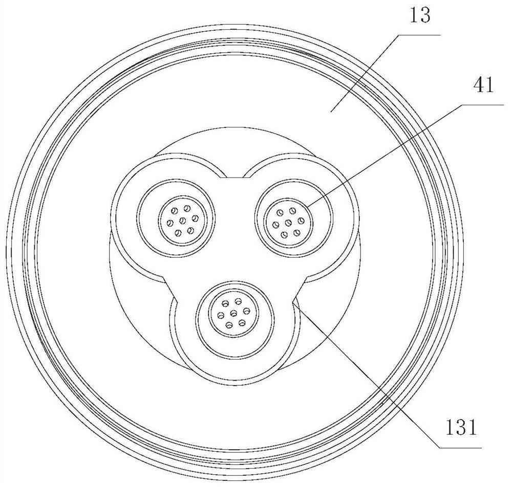
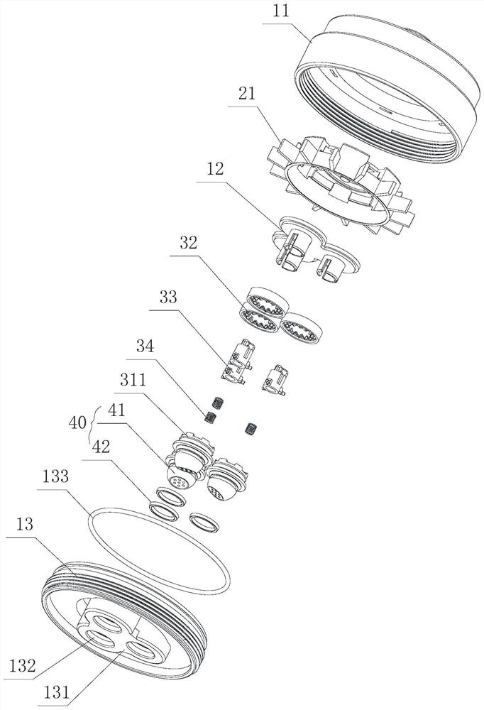
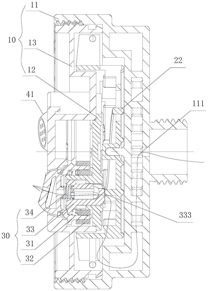
[0043] Such as figure 1 Shown, a kind of 3D rotating splash water outlet device, comprises support 10, power assembly 20, driving assembly 30 and water outlet assembly 40. Power assembly 20 is impeller 21, and impeller 21 is provided with continuous promotion ramp 22, and impeller 21 is rotatably connected to support 10, and continuous promotion ramp 22 rotates with impeller 21. The driving assembly 30 includes an upper toothed plate 31, a lower toothed plate 32, a pressing rod 33, a spring 34, and a pressing rod track piece 123 arranged on the support 10. One end of the pressing rod 33 abuts against the continuous pushing slope 22, and the pressing rod 33 The other end is provided with an inner cavity, and one end of the spring 34 extends into the inner cavity of the pressure rod 33 and exposes a portion, and the other end of the spring 34 abuts against the upper toothed plate 31 . Depression bar 33 does linear reciprocating motion along depression bar track piece 123 under ...
Embodiment 2
[0047] The main structure of this embodiment is the same as that of Embodiment 1, and the similarities will not be repeated, and the differences with Embodiment 1 are:
[0048] The upper toothed disc 31 has 12 upper helical teeth 311 altogether, and the lower toothed disc 32 is also provided with 12 lower helical teeth 321, and the upper helical teeth 311 and the lower helical teeth 321 are arranged oppositely. In this embodiment, as the impeller 21 rotates once, the pressure rod 33 moves up and down once, pushing the upper toothed plate 31 and the lower toothed plate 32 to rotate one-twelfth of 360 degrees, that is, 30 degrees, to achieve the purpose of deceleration. The present embodiment means that the speed at which the water outlet device rotates can be changed by adjusting the number of teeth of the upper toothed disc 31 and the lower toothed disc 32. Compared with embodiment 1, the present embodiment reduces the number of teeth, and the speed of rotation is faster than ...
Embodiment 3
[0050] The main structure of this embodiment is the same as that of Embodiment 1, and the similarities will not be repeated, and the difference with Embodiment 1 is:
[0051] The upper toothed disc 31 has 18 upper helical teeth 311 altogether, and the lower toothed disc 32 is also provided with 18 lower helical teeth 321, and the upper helical teeth 311 and the lower helical teeth 321 are arranged oppositely. In this embodiment, as the impeller 21 rotates once, the pressure rod 33 moves up and down once, pushing the upper toothed plate 31 and the lower toothed plate 32 to rotate one-eighteenth of 360 degrees, that is, 20 degrees, to achieve the purpose of deceleration. The present embodiment means that the speed at which the water outlet device rotates can be changed by adjusting the number of teeth of the upper toothed disc 31 and the lower toothed disc 32. Compared with embodiment 1, the present embodiment increases the number of teeth, and the speed of rotation is slower th...
PUM
 Abstract
Description
Claims
Application Information
 - R&D Engineer
- R&D Manager
- IP Professional
- Industry Leading Data Capabilities
- Powerful AI technology
- Patent DNA Extraction
Browse by: Latest US Patents, China's latest patents, Technical Efficacy Thesaurus, Application Domain, Technology Topic, Popular Technical Reports.
© 2024 PatSnap. All rights reserved.Legal|Privacy policy|Modern Slavery Act Transparency Statement|Sitemap|About US| Contact US: help@patsnap.com


