
Automatic growth rod and children scoliosis orthopedic system

A technology of automatic growth and movable rods, applied in the direction of internal fixators, internal bone synthesis, fixers, etc., can solve the problems that patients cannot accept MRI imaging examinations, can not be promoted in a large area, and the equipment is complicated, etc. It is easy to promote, Effect of reducing treatment burden and cost

Pending Publication Date: 2021-02-19
朱晓东 +2
View PDF0 Cites 4 Cited by
  • Summary
  • Abstract
  • Description
  • Claims
  • Application Information

AI Technical Summary

Problems solved by technology

Although this type of growth rod can be stretched in vivo without surgery, its stretching force is affected by the patient's posture, and it is prone to the phenomenon that it cannot be stretched. The magnetic material in the body makes the patient unable to accept the MRI examination. Complex and expensive, unable to achieve large-scale promotion

Method used


Image

  • Automatic growth rod and children scoliosis orthopedic system
  • Automatic growth rod and children scoliosis orthopedic system
  • Automatic growth rod and children scoliosis orthopedic system

Examples


Embodiment 1

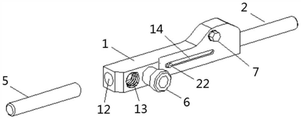
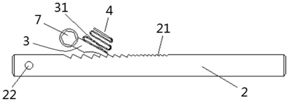
[0033] Such as Figure 1-4 As shown, the other end of the adjustment block 1 in this embodiment is provided with a second installation hole 12, and a connecting rod 5 is inserted in the second installation hole 12, and a screw plug 6 for fixing the connection rod 5 is also provided on the adjustment block 1 Specifically, a threaded hole 13 communicating with the second installation hole 12 can be provided on the adjustment block 1, the screw plug 6 is installed in the threaded hole 13, and its end is against the connecting rod 5, so that the connecting rod 5 and the adjustment Block 1 is locked, and in order to improve the firmness of fixing, the quantity of screw plug 6 can be two. The screw plug 6 realizes the detachable and fixed connection between the adjustment block 1 and the connecting rod 5, and in this embodiment, connecting rods of different strengths and sizes can be installed as required to meet various surgical requirements.

[0034] When this embodiment is appli...

Embodiment 2

[0057] This embodiment is not shown in the figure, and the basic structure is the same as that of Embodiment 1. The difference is that the two ends of the adjustment block 1 are in a symmetrical structure, that is, there are two toothed movable rods 2, which are respectively inserted into the two ends of the adjustment block 1. A telescoping structure is formed in the installation hole, and a ratchet 3 corresponding to the two movable rods 2 with teeth is arranged in the adjusting block 1 .

[0058] When this embodiment is applied to the treatment of children's scoliosis, the pedicle screw can be fixed on the vertebral body at the proximal or distal end of the spine according to the preset position, and the force is applied to make the stop teeth of the ratchet and the toothed movable rod Separate or stagger, so that the two toothed movable rods shrink at the initial position or the preset position, cancel the force to reset the pawl and be in a natural state, so that the tooth...


PUM


Abstract

The invention discloses an automatic growth rod and a children scoliosis orthopedic system, and belongs to the technical field of orthopedic implants. The automatic growth rod comprises an adjusting block and a toothed movable rod, a first mounting hole is formed in one end of the adjusting block, the toothed movable rod is inserted into the first mounting hole, limiting teeth are arranged on thetoothed movable rod, a pawl used for enabling the toothed movable rod to only move in the first mounting hole in the direction away from the adjusting block is hinged into the adjusting block, abutting teeth matched with the limiting teeth are arranged at the tail end of the pawl, and an elastic piece used for enabling the pawl to reset is further arranged in the adjusting block. In-vivo distraction can be achieved without an operation. Due to the fact that the pawl is matched with the toothed movable rod, the device is simple in structure, low in cost, easy to popularize, high in bearing capacity, safe and reliable.

Description

technical field [0001] The invention relates to the technical field of orthopedic implants, in particular to an automatic growth rod and a scoliosis correction system for children with the automatic growth rod. Background technique [0002] In recent years, with the improvement of my country's medical level, the detection rate of scoliosis in children has been increasing, and there are more and more children with scoliosis who seriously affect the appearance and even affect the cardiopulmonary function and urgently need surgical intervention. Scoliosis in young children is different from scoliosis that occurs in adolescents. If correction + fusion surgery is performed too early, it will have a greater impact on the expected height, and with bone development and weight gain, internal fixation failure may easily occur , have many adverse effects on the physical and mental health of children. Therefore, in order to protect the growth and development potential of children, scol...

Claims


Application Information

Patent Timeline
Patent Type & Authority Applications(China)
IPC IPC(8): A61B17/70
CPCA61B17/7071
Inventor 朱晓东马国强孙佳涛张勋甄超
Owner 朱晓东
Learn More