
Optical fiber beam combining structure and manufacturing method thereof

A technology of combining optical fibers and optical fibers, which is applied in the coupling of optical waveguides, light guides, optics, etc., can solve the problems of increased loss due to melting point, no longer rounded optical fibers, and damaged optical fiber shapes, so as to achieve small signal path loss and improve transmission performance , to avoid the effect of shape destruction

Inactive Publication Date: 2021-02-12
SHENZHEN XINGHAN LASER TECH CO LTD
View PDF7 Cites 1 Cited by
  • Summary
  • Abstract
  • Description
  • Claims
  • Application Information

AI Technical Summary

Problems solved by technology

[0004] The disadvantage of this method is that the temperature must reach the melting point of the optical fiber, and the optical fiber will automatically absorb into a bundle after melting. In fact, this rheology will cause great damage to the shape of the optical fiber, and the optical fiber will no longer be round, which will cause optical fiber transmission performance. This is the main reason for limiting the further improvement of the beam combiner index
In addition, in the traditional method, the optical fiber bundle needs to be cut and then fused with the output single optical fiber. The melting point will increase the loss, which is also the main reason for the inferior device index.

Method used


Image

  • Optical fiber beam combining structure and manufacturing method thereof
  • Optical fiber beam combining structure and manufacturing method thereof
  • Optical fiber beam combining structure and manufacturing method thereof

Examples


Embodiment Construction

[0023] In order to make the purpose, technical solutions and advantages of the embodiments of the present invention more clear, the technical solutions in the embodiments of the present invention will be clearly and completely described below in conjunction with the drawings in the embodiments of the present invention. Obviously, the described embodiments It is a part of embodiments of the present invention, but not all embodiments. Based on the embodiments of the present invention, all other embodiments obtained by persons of ordinary skill in the art without making creative efforts belong to the protection scope of the present invention.

[0024] In order to have a clearer understanding of the technical features, purposes and effects of the present invention, the specific implementation manners of the present invention will now be described in detail with reference to the accompanying drawings.

[0025] An embodiment of the present invention provides an optical fiber bundle ...


PUM


Abstract

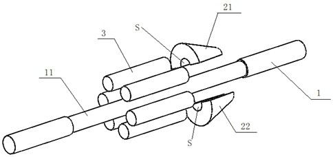
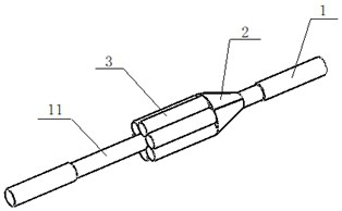
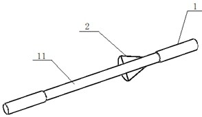
The invention provides an optical fiber beam combining structure. The optical fiber beam combining structure comprises a central optical fiber, a plurality of input optical fibers and a beam combiningcoupling and device, the beam combining and coupling device is composed of two parts, the centers of the two parts are respectively provided with a through semicircular hole, the two through semicircular holes are combined to form a through hole penetrating through the beam combining and coupling device, and the size of the through hole is matched with the size of the inner cladding of the central optical fiber; the beam combining and coupling device is sleeved on the outer surface of the inner cladding of the middle section of the central optical fiber through the through hole and is fixedlyconnected in a sintering manner; and the plurality of input optical fibers are arranged in parallel with the central optical fiber, tightly surround the central optical fiber for a circle, and are vertically welded with the pumping energy input surface in a tapering-free manner. The invention further provides a manufacturing method of the optical fiber beam combining structure and a laser. According to the invention, the tapered beam combining and coupling device is adopted, so that the shape damage caused by directly tapering a plurality of input optical fibers is avoided, and the optical fiber transmission performance is improved.

Description

technical field [0001] The invention relates to the technical field of semiconductor lasers, in particular to an optical fiber bundle structure and a manufacturing method thereof. Background technique [0002] Due to its revolutionary advantages, high-power fiber lasers have been widely used in industry, medical, military and other fields. As a key component of fiber lasers, beam combiners play an important role in the final laser indicators. The requirements of the indicators are getting higher and higher, and the industry's pursuit of fiber combiners with higher technical indicators has not stopped. [0003] Optical fiber bundling is the key process for the production of beam combiners. At present, the common practice in this industry is to clean multiple optical fibers, bind the optical fibers into a bundle by twisting method or quartz sleeve method, and then liquefy the optical fibers by high temperature. The final optical fiber is automatically attracted together to fo...

Claims


Application Information

Patent Timeline
IPC IPC(8): G02B6/255G02B6/245
CPCG02B6/245G02B6/255G02B6/2551
Inventor 周少丰刘鹏陈丕欣邢子盈
Owner SHENZHEN XINGHAN LASER TECH CO LTD
Learn More