
A periscope for pipeline inspection

A pipeline inspection and periscope technology, which is applied to pipeline systems, instruments, machines/supports, etc., can solve problems affecting the quality of camera data and periscope host shake, and achieve the effects of improving quality, reducing shaking, and improving stability

Active Publication Date: 2022-04-19
上海郎云市政工程有限公司
View PDF10 Cites 0 Cited by
  • Summary
  • Abstract
  • Description
  • Claims
  • Application Information

AI Technical Summary

Problems solved by technology

[0005] In view of the above-mentioned related technologies, the inventor believes that there may be shaking of the telescopic rod held by the operator, which will cause the main body of the periscope in the pipeline to shake, thus affecting the quality of the camera data acquired by the camera

Method used


Image

  • A periscope for pipeline inspection
  • A periscope for pipeline inspection
  • A periscope for pipeline inspection

Examples


Embodiment 1

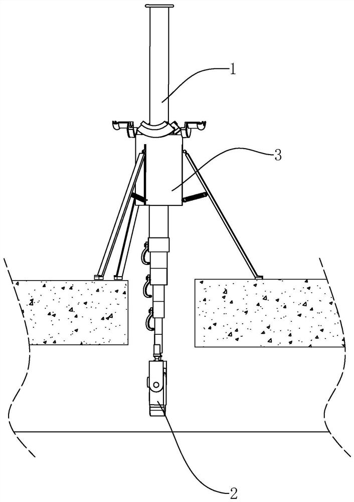
[0043] refer to figure 1 A periscope for pipeline detection includes a telescopic rod 1, a periscope host 2 inserted into the lower end of the telescopic rod 1, and a mount 3 mounted on the ground to support the telescopic rod 1, and the telescopic rod 1 is hand-held. After plugging the periscope host 2 into the lower end of the telescopic rod 1, adjust the length of the telescopic rod 1, put the periscope host 2 into the pipeline to be detected through the telescopic rod 1, and the mounting base 3 supports the telescopic rod 1 so that the periscope host 2 is in a stable position. working status.

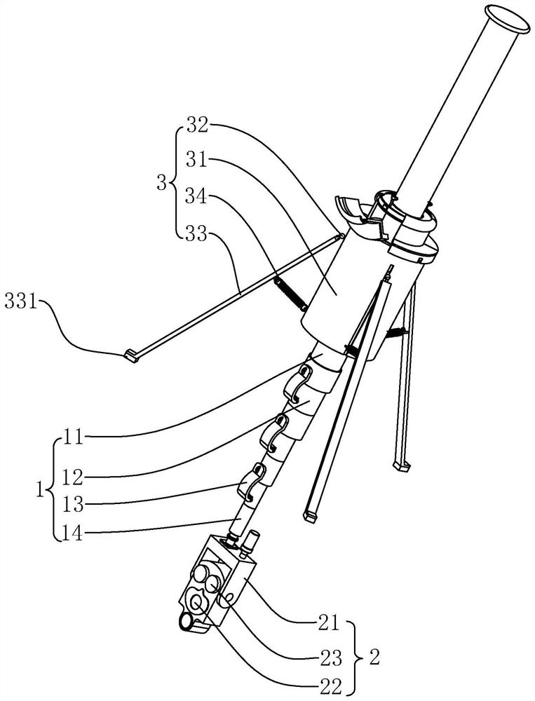
[0044] refer to figure 2 The telescopic rod 1 includes a plurality of carbon fiber tubes 11 nested in sequence, a sleeve 12 fixed between two adjacent carbon fiber tubes 11, and a tube clamp 13 hinged on the outer wall of the sleeve 12. The diameter of the plurality of carbon fiber tubes 11 is the smallest A carbon fiber pipe 11 is fixed with connecting cylinder 14. The connecti...

Embodiment 2

[0061] refer to Figure 7 The difference between this embodiment and Embodiment 1 is that the limit assembly 8 includes a plurality of limit ropes 83 fixed to the side wall of the blocking plate 5 and an insertion rod 84 for fixing the free ends of the limit ropes 83, and the limit ropes 83 The fixed end is located on the side wall of the blocking plate 5 facing the upper end of the telescopic rod 1 . An insertion hole 314 for insertion of the insertion rod 84 is defined on a peripheral side of the installation block 31 . In this embodiment, there are four limit ropes 83, and the four limit ropes 83 are arranged around the central axis of the telescopic rod 1 on the side wall of the blocking piece 5 and are respectively located in the gap between the two connected cover plates 313 .

[0062] The implementation principle of Embodiment 2 is as follows: the operator loosens the gripped telescopic rod 1 , the telescopic rod 1 is suspended in the air, and then inserts the inserti...


PUM


Abstract

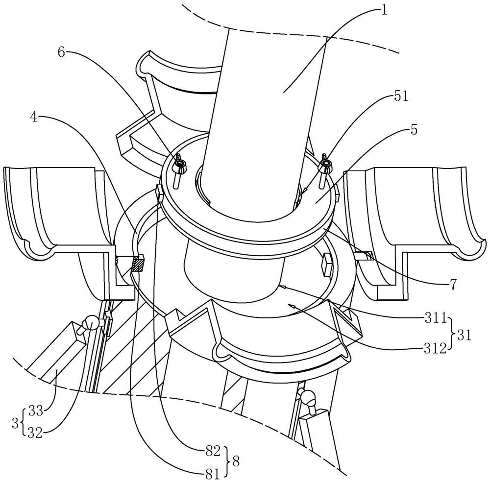
The application relates to a periscope for pipeline detection, which includes a telescopic rod, a periscope main body installed at the lower end of the telescopic rod, and a mounting seat erected on the ground; One side; the mounting seat is provided with a perforation for the telescopic rod to pass through; the side of the mounting seat facing the upper end of the telescopic rod is provided with a groove coaxially arranged with the perforation; the peripheral wall and the bottom of the groove are provided with a first magnetic block; The side of the blocking piece facing the groove and the peripheral wall of the blocking piece are provided with a third magnetic block which is opposite in polarity to the first magnetic block, so that the blocking piece is suspended in the groove. The application has the effect of improving the quality of the imaging data acquired by the camera.

Description

technical field [0001] The present application relates to the field of detection instrument technology, in particular to a periscope for pipeline detection. Background technique [0002] The pipeline periscope is used for rapid detection and diagnosis of the internal conditions of municipal rainwater and sewage pipelines, timely cleaning of garbage and foreign objects blocked in municipal pipelines and maintenance of aging pipelines, and reducing the rainwater flooding the street ground during heavy rains. [0003] The pipeline periscope is mainly composed of a control terminal, a telescopic rod, a periscope host, a support rod, and a cable. The telescoping pole is hand-held. The periscope host mainly includes a high-definition camera and a searchlight with zoom and pitch adjustment functions. [0004] After the telescopic rod adjusts the working height of the periscope host, extend the telescopic rod into the pipeline, and after the support rod touches the inner wall of t...

Claims


Application Information

Patent Timeline
Patent Type & Authority Patents(China)
IPC IPC(8): F16M11/04F16M11/28F16M7/00F16F15/04F17D5/00G03B15/02
CPCF16M11/04F16M11/28F16M7/00F16F15/03F17D5/00G03B15/02
Inventor 陈丽萍宋玉华程刚
Owner 上海郎云市政工程有限公司
Learn More