
ceramic vacuum pump

A ceramic vacuum and pump housing technology, applied in the direction of pumps, pump components, pump devices, etc., can solve problems such as poor heat dissipation performance, and achieve the effects of reducing vibration, improving safety, and improving connection tightness

Active Publication Date: 2022-05-24
奇创力真空设备(东莞)有限公司
View PDF0 Cites 0 Cited by
  • Summary
  • Abstract
  • Description
  • Claims
  • Application Information

AI Technical Summary

Problems solved by technology

[0005] The purpose of the present invention is to solve the problem of poor heat dissipation performance in the prior art, and propose a ceramic vacuum pump

Method used


Image

  • ceramic vacuum pump
  • ceramic vacuum pump
  • ceramic vacuum pump

Examples


Embodiment 1

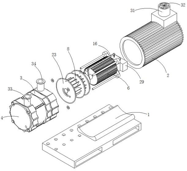
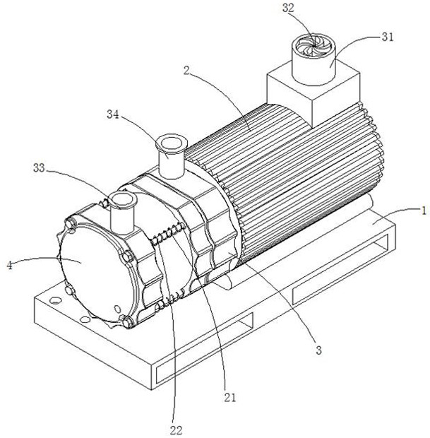
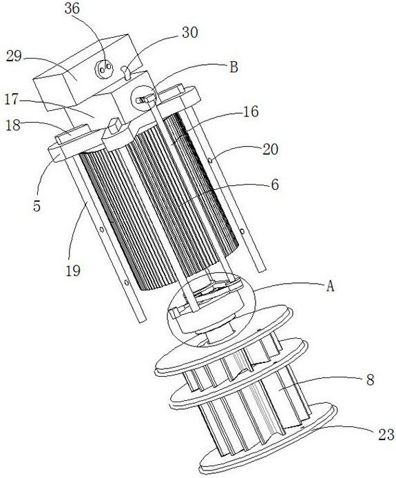
[0029] Reference Figure 1-6, a ceramic vacuum pump, comprising a base 1, a pump housing and a motor housing 2, the pump housing and the motor housing 2 are set in a horizontal direction sequentially at the top of the base 1, the pump housing comprises housing 3 and the housing cover 4, the housing cover 4 is detachablely connected to the opening of the housing 3 away from the motor housing 2, the housing 3 is fixedly connected to the motor housing 2, the motor housing 2 is installed through the X-type bracket 5 with the drive motor 6, the drive end of the drive motor 6 is connected to the transmission shaft 7, the transmission shaft 7 extends from one end of the drive motor 6 to the inner cavity of the housing 3, The extension end of the transmission shaft 7 is eccentrically disposed in the inner cavity of the housing 3, and the extension end of the transmission shaft 7 is connected to the impeller 8, the side of the housing 3 away from the shell cover 4 is rotated to be connected...

Embodiment 2

[0037] Reference Figure 1-2 , ceramic vacuum pump, and Example 1 is basically the same, further, the shell cover 4 and the housing 3 is opened with a mutually coordinated threaded mounting hole, the threaded mounting hole on the housing 3 is threaded with a connecting rod 21, the connecting rod 21 is far from the end of the housing 3 thread is connected to the shell cover 4, the housing 3 and the housing cover 4 is also fixed in the connection rod 21 outer wall of the tension spring 22, through the tension spring 22 helps to reduce the vibration when the vacuum pump works, while improving the connection tightness of the shell cover 4 and the housing 3.


PUM


Abstract

The invention discloses a ceramic vacuum pump, which comprises a base, a pump casing and a motor casing. The pump casing and the motor casing are sequentially arranged on the top of the base along the horizontal direction. The pump casing includes a casing and a casing cover, and the casing cover is detachably connected to the casing. Far away from the opening of the motor casing, the casing is fixedly connected to the motor casing. The drive motor is installed in the motor casing through an X-shaped bracket. The drive end of the drive motor is connected to the transmission shaft. The end of the transmission shaft away from the drive motor extends to the casing. In the inner cavity, the extension end of the transmission shaft is eccentrically arranged in the inner cavity of the casing, and the extension end of the transmission shaft is connected with an impeller, and the side of the casing away from the casing cover is rotatably connected to the driven pulley placed in the inner cavity of the motor casing. The shaft wall of the transmission shaft placed in the motor casing is sleeved with a transmission pulley, and the side of the casing away from the casing cover is also fixedly connected with a mounting seat; the invention realizes the shock absorption function of the vacuum pump and a good heat dissipation function at the same time, and the ceramic coating The hardness of the layer is improved, more wear-resistant, high-temperature resistant, corrosion-resistant, and the service life is increased by 4‑5 times.

Description

Technical field [0001] The present invention relates to the field of vacuum pump technology, in particular to ceramic vacuum pumps. Background [0002] Vacuum pump refers to a device or equipment that uses mechanical, physical, chemical or physical chemical methods to pump the pumped container to obtain vacuum. In layman's terms, a vacuum pump is a device that uses various methods to improve, generate and maintain vacuum in an enclosed space. [0003] According to the working principle of vacuum pump, vacuum pump can basically be divided into two types, namely gas capture pump and gas transfer pump. It is widely used in metallurgy, chemical, food, electronic coating and other industries. [0004] The disadvantage of the current vacuum pump is that the disadvantage of the vacuum pump is that it is easy to produce vibration when working, and the heat dissipation is not good, which not only affects the service life of the vacuum pump, it is easy to produce failures, but also affects...

Claims


Application Information

Patent Timeline
Patent Type & Authority Patents(China)
IPC IPC(8): F04D25/08F04D29/40F04D29/02F04D29/58F04D29/66H02K9/20H02K9/193H02K9/04
CPCF04D25/082F04D29/403F04D29/023F04D29/5806F04D29/5846F04D29/584F04D29/668H02K9/20H02K9/193H02K9/04F05D2300/20F05D2300/611F05D2300/506
Inventor 苏方宁
Owner 奇创力真空设备(东莞)有限公司
Learn More