Loader, loading system and loading method

A loader and carriage technology, applied in storage devices, transportation and packaging, loading/unloading, etc., can solve problems such as inability to stack goods on the front steps of semi-trailer carriages, and forward shifting of the center of gravity of loading and unloading equipment.

Pending Publication Date: 2021-02-12
CHINA HEFEI TAIHE OPTOELECTRONICS TECH
View PDF0 Cites 4 Cited by
  • Summary
  • Abstract
  • Description
  • Claims
  • Application Information

AI Technical Summary

Problems solved by technology

When the existing loading and unloading equipment is performing loading and unloading operations, due to the long steps in the semi-trailer compartment, the stacking device cannot stack the goods on the front steps of the semi-trailer compartment; although the stacking mobile device of some loading and unloading equipment can reach forward A certain distance, but it is easy to cause the center of gravity of the loading and unloading equipment to move forward, and there is a danger of forward tilt

Method used


Image

  • Loader, loading system and loading method
  • Loader, loading system and loading method
  • Loader, loading system and loading method

Examples


no. 1 example

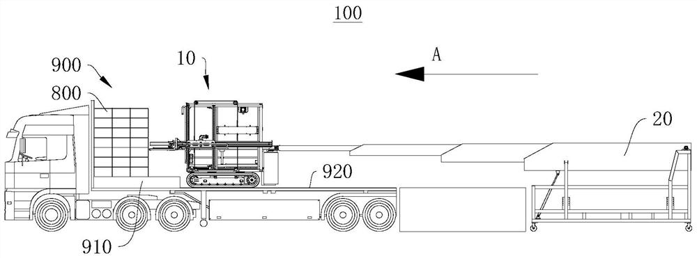
[0037] see figure 1 , figure 1 It is a schematic structural diagram of the vehicle loading machine 10 applied to the vehicle loading system 100 provided by the first embodiment of the present invention. The loading system 100 is performing loading operations in the semi-trailer compartment 900 . And the direction indicated by the arrow A in the figure is the first direction A.

[0038] The first embodiment of the present invention provides a vehicle loading machine 10. The vehicle loading machine 10 has the characteristics of being able to perform vehicle loading operations in a semi-trailer compartment 900 and having high loading stability. The vehicle loading machine 10 can be applied to a vehicle loading system 100 , a storage system or a logistics system, etc. Of course, the vehicle loading machine 10 can also be used independently.

[0039] Taking the vehicle loading machine 10 applied to the vehicle loading system 100 as an example, the vehicle loading system 100 perf...

no. 2 example

[0070] see Figure 8 , Figure 8 It is a schematic flowchart of the vehicle loading method provided by the second embodiment of the present invention.

[0071] The second embodiment of the present invention provides a vehicle loading method, which is applied to the vehicle loading machine 10 of the above embodiment. It also has the characteristics of being able to carry out loading operations in the semi-trailer compartment 900 and having high loading stability.

[0072] It should be noted that the basic principles and technical effects of the loading method provided in this embodiment are the same as those of the above-mentioned embodiment. For a brief description, the part not mentioned in this embodiment can refer to Corresponding content.

[0073] The loading method includes:

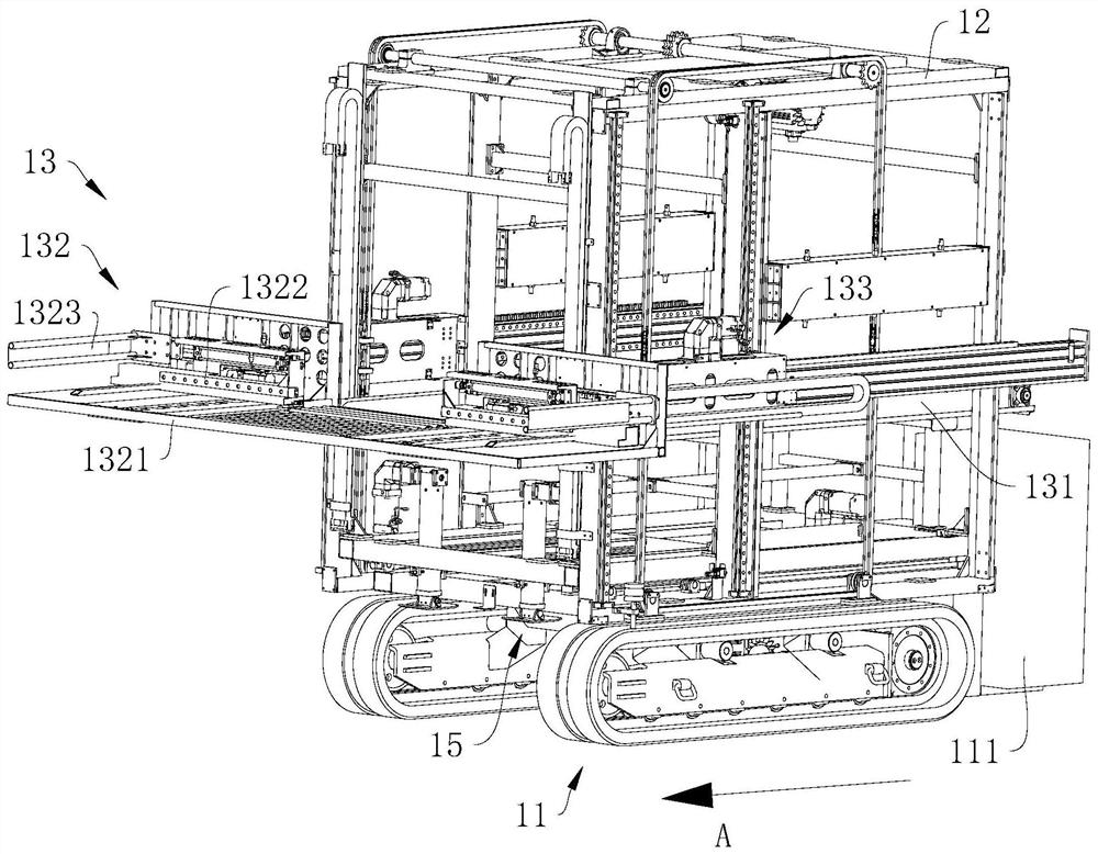
[0074] Step S101: moving the loading frame 12 forward along the first direction A, so that the loading frame 12 extends out of the traveling mechanism 11;

[0075] Step S102: Support the loadin...


PUM


Abstract

The invention discloses a loader, a loading system and a loading method, and relates to the technical field of loading. The loader comprises a walking mechanism, a loading rack, a stacking device anda supporting mechanism. The loading rack is connected to the walking mechanism in a sliding mode, and the walking mechanism can drive the loading rack to move in a semi-trailer compartment. The loading rack can move forwards in the first direction, so that the loading rack can extend out of the walking mechanism. The stacking device is slidably connected to the loading rack, can extend out of theloading rack in the first direction and is used for stacking the goods to the stacking position. The supporting mechanism is arranged on the loading rack and can abut against a step or the bottom facein the semi-trailer compartment, and therefore the loading rack is supported. The loader, the loading system and the loading method have the advantages that loading operation can be conducted in thesemi-trailer compartment, and the loading stability is high.

Description

technical field [0001] The invention relates to the technical field of vehicle loading, in particular to a vehicle loading machine, a vehicle loading system and a vehicle loading method. Background technique [0002] In the field of warehousing and logistics, the entry and exit of goods and loading and unloading trucks have always been labor-intensive links. With the aging population and rising labor costs year by year, the demand for automation of cargo handling vehicles is becoming increasingly strong. In recent years, loading and unloading equipment that can walk in the compartment has become a research hotspot. [0003] But existing loading and unloading equipment is all difficult to adapt to carrying out loading and unloading in the semi-trailer compartment. Because there is a step near the front end of the semi-trailer compartment, there is a height difference between the bottom surface of the semi-trailer compartment and the top surface of the step. When the existi...

Claims


Application Information

Patent Timeline
Patent Type & Authority Applications(China)
IPC IPC(8): B65G67/04B65G57/03B65G69/22B65G1/04
CPCB65G1/04B65G57/03B65G67/04B65G69/22
Inventor 许大红石江涛武怀斌张杰周宇
Owner CHINA HEFEI TAIHE OPTOELECTRONICS TECH
Why Eureka
Try Eureka