
Multi-stage telescopic mechanism for carrying glass in liquid crystal glass substrate production

A technology of liquid crystal glass substrate and telescopic mechanism, which is applied in the direction of conveyor objects, transportation and packaging, furnaces, etc., and can solve problems such as limited space range, large deflection of the board, and glass breakage of the substrate

Active Publication Date: 2021-02-12
彩虹(合肥)液晶玻璃有限公司
View PDF5 Cites 1 Cited by
  • Summary
  • Abstract
  • Description
  • Claims
  • Application Information

AI Technical Summary

Problems solved by technology

[0003] The existing technology has the following problems: During the entire process of handling, the upper surface of the product is not allowed to have any contact, so it is necessary to use a telescopic handling mechanism to lower the glass substrate The surface is extended in, and then the substrate glass is lifted to achieve the purpose of transfer. However, the current handling claws are limited by the limited space. If the opening is too large, it will interfere with the peripheral equipment, but if the opening is too small, it will fall. It interferes with the substrate glass, so in order to achieve the purpose of handling, the lower supporting claws cannot be extended too long, resulting in the lower claws being too short when handling the glass and can only hold up a limited range of the edge of the board, so that the middle of the board is suspended too much, resulting in the middle Due to the sinking of gravity, the deflection of the board is too large, which affects the accuracy of positioning, and it is also easy to cause the substrate glass to break due to the gravity in the middle

Method used


Image

  • Multi-stage telescopic mechanism for carrying glass in liquid crystal glass substrate production
  • Multi-stage telescopic mechanism for carrying glass in liquid crystal glass substrate production
  • Multi-stage telescopic mechanism for carrying glass in liquid crystal glass substrate production

Examples


Embodiment Construction

[0033] The following will clearly and completely describe the technical solutions in the embodiments of the present invention with reference to the accompanying drawings in the embodiments of the present invention. Obviously, the described embodiments are only some, not all, embodiments of the present invention. Based on the embodiments of the present invention, all other embodiments obtained by persons of ordinary skill in the art without making creative efforts belong to the protection scope of the present invention.

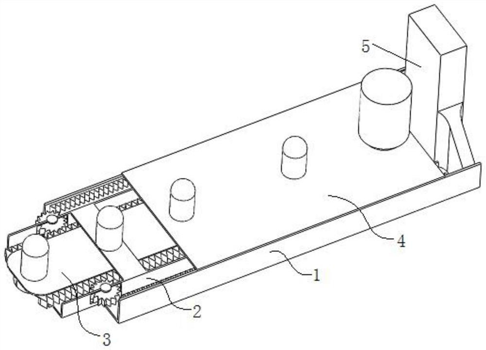
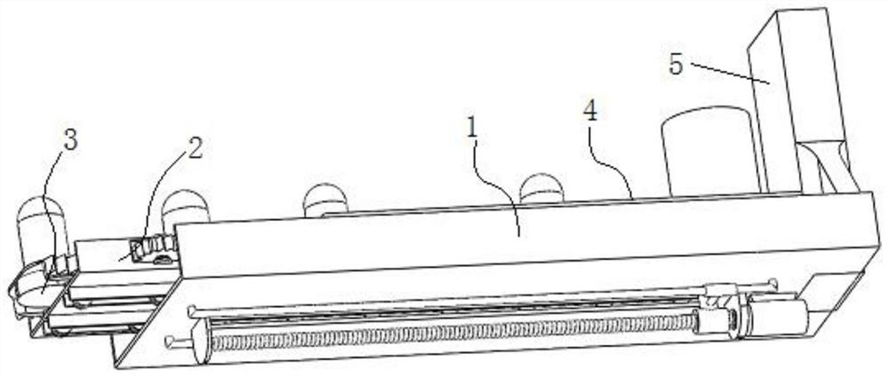
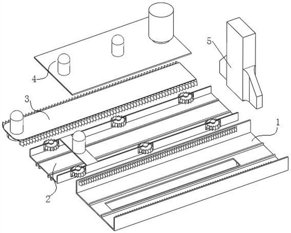
[0034] see Figure 1-13 , the present invention provides the following technical solutions: a multi-stage telescopic mechanism for handling glass in the production of liquid crystal glass substrates, comprising a first-stage telescopic support arm assembly 1, one end of the first-stage telescopic support arm assembly 1 is fixedly provided with an end fixed connection Boom rod 5, and the internal expansion of the primary telescopic support arm assembly 1 is pro...


PUM


Abstract

The invention discloses a multi-stage telescopic mechanism for carrying glass in liquid crystal glass substrate production. The multi-stage telescopic mechanism comprises a first-stage telescopic support arm assembly, an end part fixed connecting arm frame rod is fixedly arranged at one end of the first-stage telescopic support arm assembly, and a second-stage telescopic support arm assembly is telescopically arranged in the first-stage telescopic support arm assembly. A third-stage telescopic support arm assembly is telescopically arranged in the second-stage telescopic support arm assembly.A U-shaped second-stage telescopic support arm frame plate telescopically moves in a U-shaped first-stage telescopic support arm frame plate through left-right reciprocating movement of an inner threaded pipe on a threaded rod, and when the U-shaped second-stage telescopic support arm frame plate telescopically moves in the U-shaped first-stage telescopic support arm frame plate, a plate body of arectangular tertiary telescopic support arm frame plate telescopically moves in the U-shaped second-stage telescopic support arm frame plate through the matching of a rotating gear, a first-stage rack plate and a third-stage rack plate.

Description

technical field [0001] The invention belongs to the technical field of liquid crystal substrate glass production, and in particular relates to a multi-stage telescopic mechanism for transporting glass in the production of liquid crystal glass substrates. Background technique [0002] At present, in the production of liquid crystal glass substrates, during the edging process of the glass, the glass needs to be carried by the handling claws to realize rotation and displacement, so as to complete the edging and chamfering of the four sides. [0003] The existing technology has the following problems: During the whole process of transportation, the upper surface of the product is not allowed to have any contact, so it is necessary to use a telescopic transportation mechanism to extend from the lower surface of the glass substrate, and then lift the substrate glass to achieve the purpose of transfer. However, the current handling claws are limited by space limitations. If the ope...

Claims


Application Information

Patent Timeline
IPC IPC(8): B65G49/06
CPCB65G49/062Y02P40/57
Inventor 郭拴军
Owner 彩虹(合肥)液晶玻璃有限公司
Learn More