
Automatic industrial fire extinguishing device based on Internet of Things

A fire extinguishing device and industrial technology, applied in motor vehicles, fire rescue, transportation and packaging, etc., can solve the problems of excessive energy consumption, cumbersome use and operation, unfavorable firefighting work, etc., to achieve good fire extinguishing, energy saving, and direction range small effect

Inactive Publication Date: 2021-02-12
衡阳市华毅自动化科技有限公司
View PDF11 Cites 0 Cited by
  • Summary
  • Abstract
  • Description
  • Claims
  • Application Information

AI Technical Summary

Problems solved by technology

[0003] China's public authorized invention: CN206964935U discloses a multifunctional industrial fire extinguishing device, which is provided with a base, a support plate, a box body, a water outlet pipe, a water pump, a second sprinkler pipe, a diverter pipe, a first sprinkler pipe, and a first valve , sprinkler, first drain pipe, second valve, second drain pipe, hose, runner and water gun solve the problem of single function of the existing industrial fire extinguishing device. , after the device stops, the direction and angle of fire extinguishing cannot be adjusted without moving the device itself. The operation is cumbersome, and the direction of the body needs to be adjusted frequently, which consumes more physical strength, which is not conducive to the fire protection work, and the equipment in the workshop uses dry powder The effect of fire extinguishing will be better. This device is not equipped with a dry powder fire extinguisher. Therefore, an automated industrial fire extinguishing device based on the Internet of Things is proposed.

Method used


Image

  • Automatic industrial fire extinguishing device based on Internet of Things
  • Automatic industrial fire extinguishing device based on Internet of Things
  • Automatic industrial fire extinguishing device based on Internet of Things

Examples


Embodiment

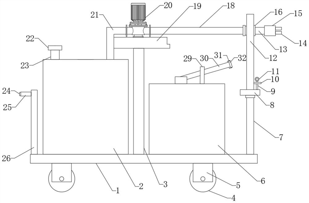
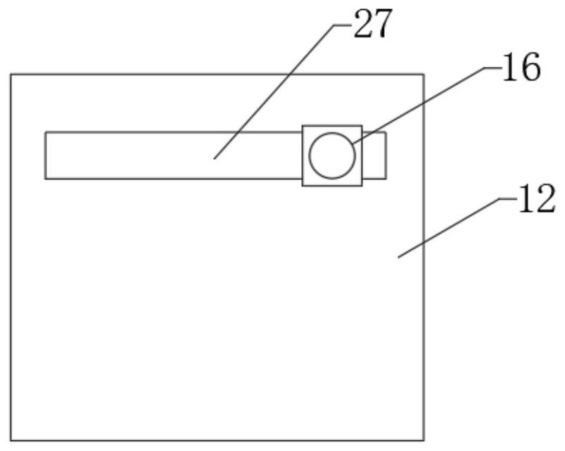
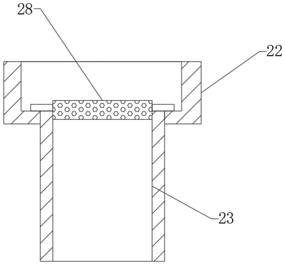
[0021] see Figure 1-3 , the present invention provides a technical solution: an automatic industrial fire extinguishing device based on the Internet of Things, including a base plate 1, a support column a-3 is welded on the upper surface of the base plate 1, and a plate body is welded on the upper surface of the support column a-3 c-19, the water pump 20 is installed on the upper surface of the plate body c-19, the water tank 2 is welded on the upper surface of the bottom plate 1, the water inlet of the water pump 20 is connected with a water pipe b-21, and one end of the water pipe b-21 runs through the inside of the water tank 2 The top wall is connected with the inside of the water tank 2, and the upper surface of the bottom plate 1 is welded with a support column b-7. The vertical plate 12, the inner side wall of the vertical plate 12 is provided with a chute 27, the inner side wall of the chute 27 is slidably connected with the connecting pipe b-16, the water outlet of t...


PUM


Abstract

The invention discloses an automatic industrial fire extinguishing device based on Internet of Things. The automatic industrial fire extinguishing device based on Internet of Things comprises a bottomplate, wherein a supporting column a is welded to the upper surface of the bottom plate, a plate body c is welded to the upper surface of the supporting column a, a water pump is mounted on the uppersurface of the plate body c, a water tank is welded to the upper surface of the bottom plate, a water pipe b communicates to a water inlet of the water pump, one end of the water inlet pipe b penetrates through the inner top wall of the water tank and communicates within the water tank, a supporting column b is welded to the upper surface of the bottom plate, one end of the supporting column b isrotatably connected to a plate body a through a bearing, and a water pump transfers water in the water tank to a connecting pipe b. A water spraying angle for fire extinguishment can be adjusted, anddirections of the connecting pipe b and a nozzle can be changed without adjusting the direction of a vehicle body, so that the physical labor is saved. The direction range of spraying of dry powder in a dry powder storage tank is smaller and the dry powder is centralized to fire extinguishing pints, so that equipment can be extinguished better.

Description

technical field [0001] The invention relates to the technical field of fire extinguishing devices, in particular to an automatic industrial fire extinguishing device based on the Internet of Things. Background technique [0002] Industrial workshops are equipment-intensive areas where oil, electricity and flammable materials are scattered on the ground. Fire prevention has always been the top priority. At present, the common fire prevention measures in industrial workshops mainly include fire hydrant fire prevention, fire extinguisher fire extinguishing, etc. Among them, fire hydrant fire extinguishing requires a lot of water, laying water pipes and opening fire hydrants. In addition, water will cause certain damage to the equipment and cause secondary losses, while fire extinguishers usually only work against small fire sources, and will also bring certain potential dangers to the operator. Industrial fire extinguishing device is an essential equipment for a factory. [0...

Claims


Application Information

Patent Timeline
IPC IPC(8): A62C31/03A62C31/00A62C31/28B62B3/00B62B5/00
CPCA62C31/00A62C31/03A62C31/28B62B3/00B62B5/00
Inventor 胡耀华周前铁张睿智王艺丰
Owner 衡阳市华毅自动化科技有限公司
Learn More