Imaging module, forming method thereof and lens assembly
A technology of imaging modules and piezoelectric elements, which is applied in the fields of electrical components, image communication, and electric solid-state devices, and can solve problems such as large space occupation, insufficient driving ability, and complex structure
- Summary
- Abstract
- Description
- Claims
- Application Information
AI Technical Summary
Problems solved by technology
Method used
Image

Examples
Embodiment 1
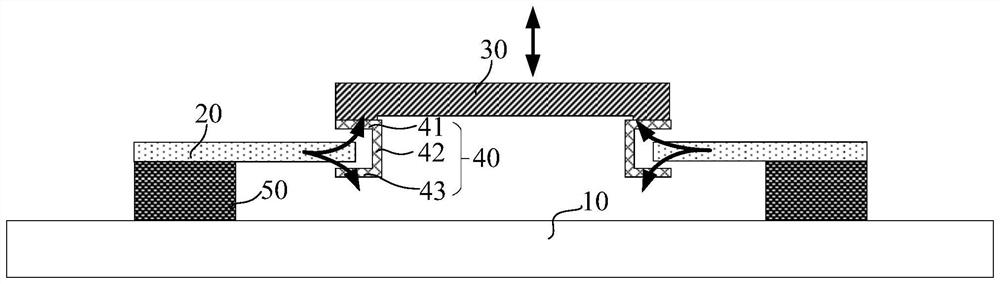
[0104] Such as figure 1 As shown, this embodiment provides an imaging module, including:
[0105] A moved element 30, which is a lens group, a single lens sheet or an aperture;
[0106] The limit groove 40 is fixed on the surface of the moved element 30, the surface of the moved element 30 refers to the upper surface, lower surface or side surface of the moved element 30;
[0107] A piezoelectric element 20 comprising a movable end and a fixed end, the movable end extends into the limiting groove 40 and is wholly or partly located in the limiting groove 40, the limiting groove 40 is the movable end providing a moving space, when the piezoelectric element 20 is in an energized state, the movable end warps upward or downward relative to the fixed end to move the moved element 30;
[0108] A support block 50 is used to support and fix the piezoelectric element 20, and the fixed end is fixed to the support block 50;
[0109] The external signal connection end is electrically co...
Embodiment 2
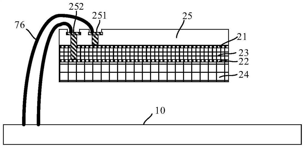
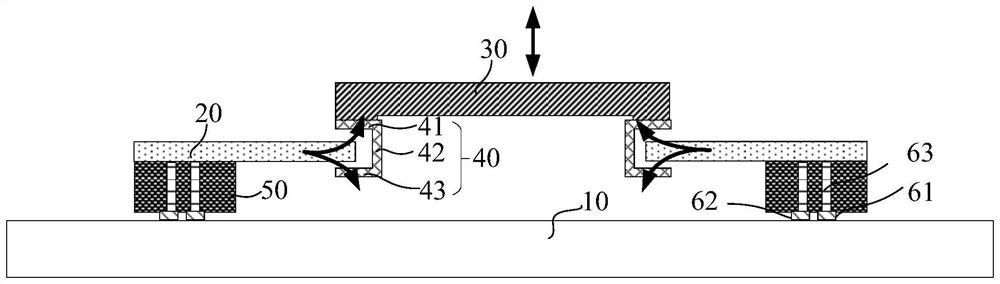
[0138] The difference from Embodiment 1 is that in this embodiment, if Figure 11 As shown, the fixed end of the piezoelectric element 20 is inserted into the support block 50 for fixing.
[0139] The support block 50 includes a first layer support block 51 and a second layer support block 52 stacked in sequence from bottom to top, and the fixed end of the piezoelectric element 20 is fixed to the first layer support block 51 and the second layer support block. between blocks 52. The support block 50 of the present invention is not limited to only including two layers of support blocks, and may also include one layer, three layers, four layers, five layers, etc., as long as the fixed end of the piezoelectric element 20 is inserted into the support block 50 Just fix it.
[0140] see Figure 11 and figure 2 , when the first lead-out end 251 and the second lead-out end 252 are located on the top surface of the piezoelectric element 20, the external signal connection end inclu...
Embodiment 3
[0145] The difference from Embodiment 1 and Embodiment 2 is that in this embodiment, the moved element 30 is an imaging sensing element.
[0146] Such as Figure 14 with Figure 15a As shown, the top surface of the piezoelectric element 20 is also provided with a wiring layer 75, the wiring layer 75 is located in the insulating layer 25, and both ends have a first electrical connection terminal 71 exposing the insulating layer 25 and The fifth electrical connection terminal 74 . The first electrical connection end 71 is closer to the moved element 30 than the fifth electrical connection end 74, the upper surface of the moved element 30 is provided with a second electrical connection end 72, the first electrical connection end 71 and the second electrical connection end 72 are electrically connected through a flexible connector 73, and then a lead wire 76 is used to electrically connect the fifth electrical connection end 74 to the circuit board 10, so that the circuit board ...
PUM
 Abstract
Description
Claims
Application Information
 - R&D
- Intellectual Property
- Life Sciences
- Materials
- Tech Scout
- Unparalleled Data Quality
- Higher Quality Content
- 60% Fewer Hallucinations
Browse by: Latest US Patents, China's latest patents, Technical Efficacy Thesaurus, Application Domain, Technology Topic, Popular Technical Reports.
© 2025 PatSnap. All rights reserved.Legal|Privacy policy|Modern Slavery Act Transparency Statement|Sitemap|About US| Contact US: help@patsnap.com