Eureka AIR delivers breakthrough ideas for toughest innovation challenges, trusted by R&D personnel around the world.

A kind of in-phase traction power supply power generation system and control method

A power generation system and traction power supply technology, applied in photovoltaic power generation, electric traction, AC networks with the same frequency from different sources, etc. The effect of promoting green development

Active Publication Date: 2021-04-13
SOUTHWEST JIAOTONG UNIV
View PDF15 Cites 0 Cited by
  • Summary
  • Abstract
  • Description
  • Claims
  • Application Information

AI Technical Summary

Problems solved by technology

However, it is clear that the power of new energy trains is strictly limited by their own weight and volume, and cannot meet the requirements of high-power traction. Therefore, it is necessary to propose a high-power new energy utilization plan suitable for the characteristics of the traction power supply system. At the same time, it should be connected to the traction power supply system. The power flow control method for new energy power generation needs to be formulated according to its traction load characteristics, which is completely different from the power flow control method for grid-connected power generation and the power flow control method for new energy train power generation.

Method used


Image

  • A kind of in-phase traction power supply power generation system and control method
  • A kind of in-phase traction power supply power generation system and control method
  • A kind of in-phase traction power supply power generation system and control method

Examples


Embodiment 1

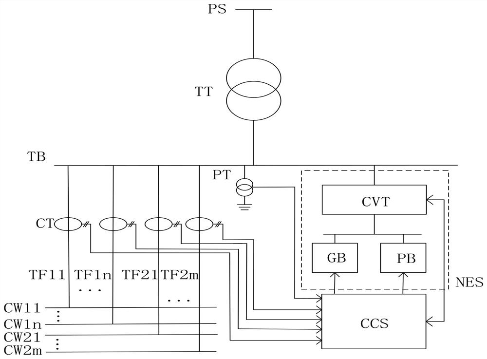
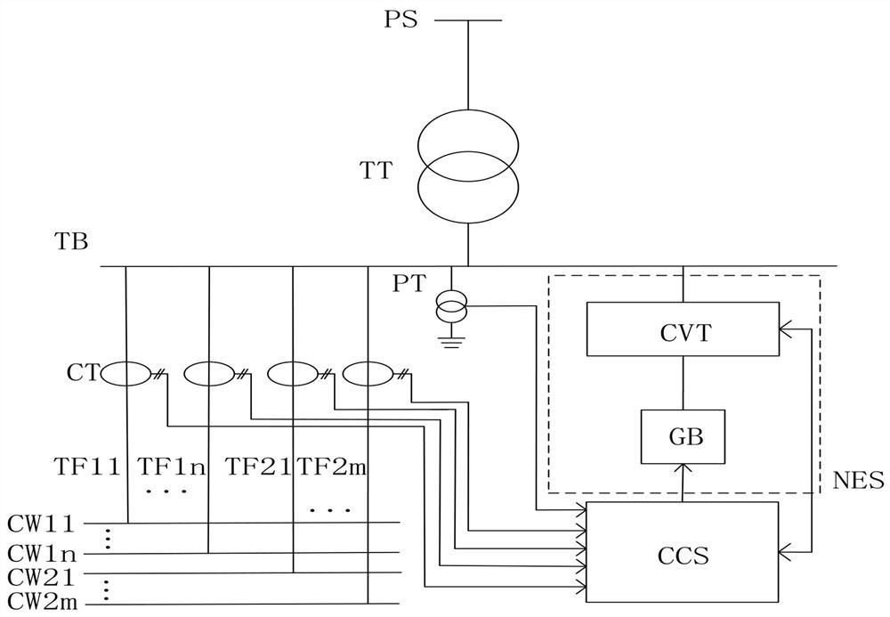
[0033] like figure 1 As shown, this embodiment provides an in-phase traction power supply power generation system, including a traction transformer TT, a traction bus TB and a feeder TF, and the secondary side of the traction transformer TT is connected to the traction bus TB. It is characterized in that: the traction bus TB is provided with There is a voltage transformer PT, and the AC output terminal of the new energy power generation device NES is connected to the traction bus TB. The feeder TF is divided into n upstream feeder lines TF11, TF12, ..., TF1n and m downstream feeder lines TF21, TF22, ..., TF2m , each upstream feeder and each downstream feeder are equipped with a current transformer CT, n≥2, m≥2, wherein: the first ends of the n upstream feeders TF11, TF12, ..., TF1n are connected to the traction bus TB Connection, the end of n uplink feeders TF11, TF12, ..., TF1n is connected to n uplink catenary lines CW11, CW12, ..., CW1n; Connection, m downlink feeder lines...

Embodiment 2

[0043] like Figure 4 As shown, this embodiment provides a control method based on the same-phase traction power supply power generation system provided in Embodiment 1, which is applied to the coordination controller CCS, and the method includes:

[0044] S1: The coordinating controller CCS obtains the voltage information measured by the voltage transformer PT and the current information measured by each current transformer CT; S2: According to the voltage information and current information, n upstream feeder lines TF11 and TF12 are calculated respectively , ..., the active power P11, P12, ..., P1n of TF1n and the active power P21, P22, ..., P2m of m downlink feeders TF21, TF22, ..., TF2m, where the active power flowing to the catenary is the traction power, denoted as Positive, active power flowing to the traction bus is regenerative power, recorded as negative;

[0045] S3: The active power P11, P12, ..., P1n of the n uplink feeder lines TF11, TF12, ..., TF1n are summed t...


PUM


Abstract

The invention provides an in-phase traction power supply power generation system and a control method, which relate to the technical field of electrified railway power supply. The secondary side of the traction transformer is connected to the traction busbar; the first ends of the n uplink feeders are all connected to the traction busbar, the tail ends of the n uplink feeder lines are correspondingly connected to n uplink catenary lines, and the first ends of the m downlink feeder lines are all connected to the traction busbar , the tail ends of the m downlink feeders are connected to the m downlink catenary; the input end of the coordinating controller is connected with the measuring end of the voltage transformer and the current transformer at the same time, and the output end of the coordinating controller is connected with the new energy power generation The console connection of the device. The AC output end of the new energy power generation device is connected to the traction busbar. The invention not only facilitates the nearby consumption of new energy, promotes the green development of the railway system, avoids related power quality problems, but also brings additional economic income.

Description

technical field [0001] The invention relates to the technical field of AC electrified railway power supply. Background technique [0002] The application of new energy and renewable energy to power generation has been widely used in the power system, and the power generation has increased year by year, and the progress has been remarkable. [0003] The flow of new energy, renewable energy and grid-connected power generation is controlled according to the grid-connected voltage phase. The new energy train power generation is an independent small system, and its flow is controlled by voltage regulation and frequency regulation. However, it is clear that the power of new energy trains is strictly limited by their own weight and volume, and cannot meet the requirements of high-power traction. Therefore, it is necessary to propose a high-power new energy utilization plan suitable for the characteristics of the traction power supply system. At the same time, it should be connected...

Claims


Application Information

Patent Timeline
Patent Type & Authority Patents(China)
IPC IPC(8): H02J3/38H02J3/01H02J3/46H02J3/18H02J3/32H02J3/06B60L9/00
CPCB60L9/00H02J3/01H02J3/06H02J3/18H02J3/32H02J3/381H02J3/466H02J2203/10H02J2203/20H02J2300/24H02J2300/28H02J2300/30H02J2300/40Y02E10/56Y02E40/30Y02E40/40
Inventor 李群湛李子晗张伟鹏黄小红吴波郭锴解绍锋易东张丽艳
Owner SOUTHWEST JIAOTONG UNIV
Why Eureka
Eureka Blog
Learn More