
Protection device for refrigeration equipment

A technology for protection devices and refrigeration equipment, applied in household refrigeration devices, lighting and heating equipment, applications, etc., can solve the problems of wear and tear of refrigeration equipment and protection equipment, incomplete protection of refrigeration equipment, etc. Effect

Inactive Publication Date: 2021-02-09
陕西钧诚建鑫机电工程有限公司
View PDF1 Cites 0 Cited by
  • Summary
  • Abstract
  • Description
  • Claims
  • Application Information

AI Technical Summary

Problems solved by technology

[0006] The purpose of the present invention is to solve the problem that the protective device of the refrigeration equipment in the prior art does not fully protect the refrigeration equipment and the problem of easy wear between the refrigeration equipment and the protection equipment, and proposes a protection device for refrigeration equipment

Method used


Image

  • Protection device for refrigeration equipment
  • Protection device for refrigeration equipment

Examples


Embodiment 1

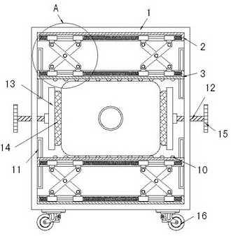
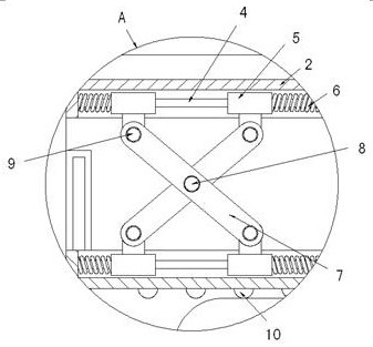
[0023] Example 1 as figure 1 As shown, the protective device for refrigeration equipment includes a housing 1 and a fixed plate 2, the two fixed plates 2 are respectively fixed at both ends inside the housing 1, and the inner sides of the two fixed plates 2 are provided with movable plates 3 , the inner sides of multiple movable plates 3 are all rollingly provided with a plurality of balls 10, both ends of the inner side walls of the housing 1 are fixedly provided with limiting plates 11, and the surfaces of the plurality of limiting plates 11 are all provided with limiting grooves. Both ends of each movable plate 3 are slidably connected with the corresponding limit grooves through the limit block, and the sides near the fixed plate 2 and the movable plate 3 on both sides are provided with grooves, and the insides of the plurality of grooves are all fixedly provided with Slider 4, two sliders 5 are movably socketed at both ends of a plurality of sliders 4, and the plurality o...

Embodiment 2

[0024] Embodiment 2 is on the basis of embodiment 1 such as figure 1 As shown, its clamping mechanism includes a threaded rod 12 and a rubber splint 14. The two threaded rods 12 are arranged on both sides of the housing 1 and are screwed to the corresponding side walls of the housing 1. The two threaded rods 12 are Both inner ends extend to the inside of the housing 1 and are provided with connecting plates 13 rotatably through rolling bearings, and two rubber splints 14 are fixedly arranged on the inner sides of the corresponding connecting plates 13 .

Embodiment 3

[0025] Embodiment 3 is such as on the basis of embodiment 1 figure 2 As shown, its plurality of springs 6 are all compression springs, which will push the corresponding slider 5 inward in a natural state.


PUM


Abstract

The invention relates to the technical field of protection devices, and discloses a protection device for refrigeration equipment. The protection device comprises a shell and fixed plates, wherein thetwo fixed plates are fixedly arranged at the two ends of the interior of the shell correspondingly; movable plates are arranged on the inner sides of the two fixed plates, and a plurality of balls are arranged on the inner sides of the plurality of movable plates in a rolling mode; limiting plates are fixedly arranged at the two ends of the two side walls of the interior of the shell, limiting grooves are formed in the surfaces of the plurality of limiting plates, and the two ends of the plurality of movable plates are slidably connected with the corresponding limiting grooves through limiting blocks; and grooves are formed in the sides, close to the movable plates, of the fixed plates on the two sides, sliding rods are fixedly arranged inside the plurality of grooves, and the two ends ofeach of the plurality of sliding rods are movably connected with two sliding blocks in a sleeved mode. According to the protection device for the refrigeration equipment, comprehensive buffer protection can be achieved on the refrigeration equipment, and the friction loss between the movable plates and the refrigeration equipment can be reduced.

Description

technical field [0001] The invention relates to the technical field of protection devices, in particular to a protection device for refrigeration equipment. Background technique [0002] Refrigeration equipment is a device that combines a refrigerator with a facility that uses cold energy. The refrigeration device is designed and constructed to effectively use cold energy to refrigerate food or other items; conduct product performance tests and scientific research tests at low temperatures; Realize certain cooling processes in industrial production, or perform air conditioning. Refrigeration equipment needs to be fixed and protected during work or transportation to reduce damage caused by vibration and friction. Only better protection of equipment can increase the service life of refrigeration equipment as much as possible. [0003] Wherein the patent No. CN207065976U discloses a protection device for refrigeration equipment. When in use, the refrigeration equipment is fixe...

Claims


Application Information

Patent Timeline
Patent Type & Authority Applications(China)
IPC IPC(8): F25D23/06B60B33/00F16F15/08
CPCB60B33/00F16F15/08F25D23/062
Inventor 姜晓红
Owner 陕西钧诚建鑫机电工程有限公司
Learn More