Eureka AIR delivers breakthrough ideas for toughest innovation challenges, trusted by R&D personnel around the world.

Engineering non-fines concrete water storage and pressure relief well anti-floating structure and implementation method thereof

A technology of sand-free concrete and pressure relief wells, which is applied in basic structure engineering, drainage, earthwork drilling, etc., can solve the problems of uncontrollable construction process and insufficient buoyancy resistance of underground floor structure, and achieve the effect of reducing buoyancy and lowering water level.

Pending Publication Date: 2021-02-09
中矿金业股份有限公司
View PDF6 Cites 2 Cited by
  • Summary
  • Abstract
  • Description
  • Claims
  • Application Information

AI Technical Summary

Problems solved by technology

[0005] The object of the present invention is to provide an anti-floating structure of an engineering sand-free concrete water storage and pressure relief well and its implementation method to solve the problem that the underground engineering construction needs to be excavated very deep in the process of underground space utilization proposed in the above-mentioned background technology. As a result of the foundation pit, the foundation is buried in a deep stratum. The designers will carefully consider the geological conditions and engineering conditions. The floor structure often has problems with insufficient buoyancy resistance

Method used


Image

  • Engineering non-fines concrete water storage and pressure relief well anti-floating structure and implementation method thereof
  • Engineering non-fines concrete water storage and pressure relief well anti-floating structure and implementation method thereof
  • Engineering non-fines concrete water storage and pressure relief well anti-floating structure and implementation method thereof

Examples


Embodiment Construction

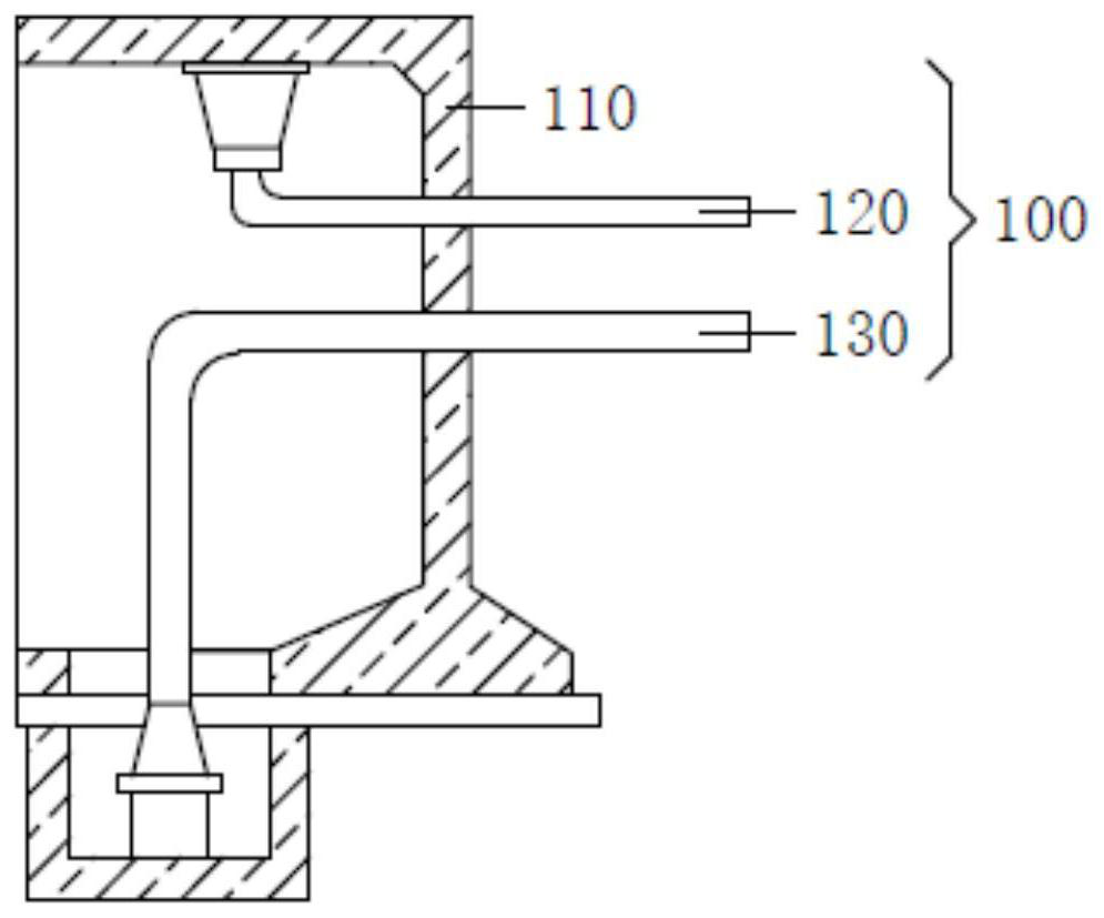
[0028] The following will clearly and completely describe the technical solutions in the embodiments of the present invention with reference to the accompanying drawings in the embodiments of the present invention. Obviously, the described embodiments are only some, not all, embodiments of the present invention. Based on the embodiments of the present invention, all other embodiments obtained by persons of ordinary skill in the art without making creative efforts belong to the protection scope of the present invention.

[0029] The invention provides an anti-floating structure of an engineering sand-free concrete water storage and pressure relief well, which can collect groundwater, thereby reducing the buoyancy on the bottom of the emergency pool, playing an anti-floating role, and supplying other places through the collected groundwater for production and greening Water, supplying production and domestic water, please refer to figure 1 , including: an emergency pool 100 and ...


PUM

PropertyMeasurementUnit
Thicknessaaaaaaaaaa
The inside diameter ofaaaaaaaaaa

Abstract

The invention discloses an engineering non-fines concrete water storage and pressure relief well anti-floating structure and an implementation method thereof, and relates to the technical field of mines. The engineering non-fines concrete water storage and pressure relief well anti-floating structure comprises an emergency pool and a water storage and pressure relief well, wherein the water storage and pressure relief well is arranged at a water source gushing point on the edge of the emergency pool. The emergency pool comprises an emergency pool body, an overflow pipe and a drainage pipe, theoverflow pipe is installed at the top of an inner cavity of the emergency pool body, the drainage pipe is installed at the bottom of the inner cavity of the emergency pool body, and the drainage pipecorresponds to the overflow pipe. The water storage and pressure relief well comprises a gravel layer and a shaft, the gravel layer is buried under the ground, the shaft is arranged at the top of thegravel layer, and part of the shaft is arranged under the ground. According to the engineering non-fines concrete water storage and pressure relief well anti-floating structure and the implementationmethod thereof, underground water can be collected, so that the buoyancy to the bottom of the emergency pool is reduced, the anti-floating effect is achieved, and the collected underground water is supplied to other places as production and greening water and is supplied for production and domestic water.

Description

technical field [0001] The invention relates to the technical field of mines, in particular to an anti-floating structure of an engineering sandless concrete water storage pressure relief well and an implementation method thereof. Background technique [0002] Mine refers to an independent production and operation unit that extracts ore with a certain mining boundary. Mine mainly includes one or more mining workshops (or pitheads, mine shafts, open pits, etc.) and some auxiliary workshops, and most mines also include ore dressing plants (coal washing plants). Mines include coal mines, metal mines, non-metal mines, building materials mines and chemical mines, etc. Mine scale (also known as production capacity) is usually expressed by annual output or daily output. Annual output refers to the amount of ore produced by a mine every year. According to the size of output, it is divided into three types: large, medium and small. The size of the mine should be compatible with t...

Claims


Application Information

Patent Timeline
IPC IPC(8): E02D31/10E02D31/12E21F16/00
CPCE02D31/10E02D31/12E21F16/00
Inventor 陈飞王其波张好和刁生杰滕玉雷杜兴业
Owner 中矿金业股份有限公司
Why Eureka
Eureka Blog
Learn More