
Chip with charging and discharging control circuit

A charge-discharge control and charge-discharge management technology, applied in battery circuit devices, charging/discharging current/voltage regulation, circuit devices, etc., can solve problems such as terminal chip identification errors and long charging time

Pending Publication Date: 2021-02-05
上海坚芯电子科技有限公司
View PDF0 Cites 0 Cited by
  • Summary
  • Abstract
  • Description
  • Claims
  • Application Information

AI Technical Summary

Problems solved by technology

The external external large capacitor can maintain the terminal chip to maintain normal operation during the long-term power-off process, but the external large capacitor will also cause the terminal chip to charge too long during the power-on process, so that the terminal chip cannot respond to commands from the host in a timely manner. In case of misidentification

Method used


Image

  • Chip with charging and discharging control circuit
  • Chip with charging and discharging control circuit

Examples


Embodiment Construction

[0034] The following will clearly and completely describe the technical solutions in the embodiments of the present invention with reference to the accompanying drawings in the embodiments of the present invention. Obviously, the described embodiments are only some, not all, embodiments of the present invention. Based on the embodiments of the present invention, all other embodiments obtained by persons of ordinary skill in the art without creative efforts fall within the protection scope of the present invention.

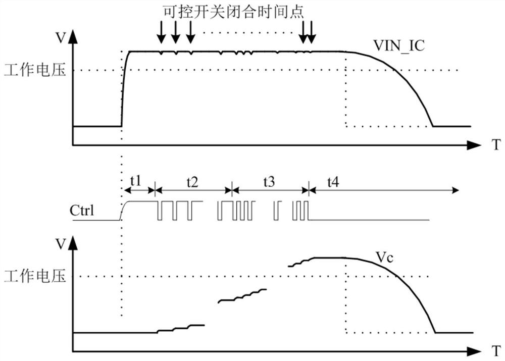
[0035] refer to figure 1 , is a schematic structural diagram of a chip with a charge and discharge control circuit provided by an embodiment of the present invention. The chip with charge and discharge control circuit includes a total input terminal 1, a total output terminal 2, a one-way conduction module 3 and a charge and discharge module 4; wherein,

[0036] The total input terminal 1 is connected to the input terminal of the unidirectional conduction module 3...


PUM


Abstract

According to a chip with a charging and discharging control circuit, provided by the invention, the charging and discharging control circuit is formed by arranging a one-way conduction module and a charging and discharging module, and the one-way conduction module is used for controlling current from an external power supply to be transmitted to the charging and discharging control module in a one-way mode; a charging and discharging management unit in the charging and discharging module is used for controlling the on or off state of a controllable switch unit, the charging and discharging management unit can select PWM pulse signals with different duty cycles to charge the energy storage unit or supply power to the chip, the circuit structure is simple, and the area of the chip can be reduced; and moreover, a large capacitor is introduced as an energy storage unit to prolong the charging and discharging time without affecting the power-on time of the chip, thereby guaranteeing the working continuity and stability of the chip, and effectively avoiding the data loss of the chip.

Description

technical field [0001] The invention relates to the technical field of chip power supply circuits, in particular to chips with charge and discharge control circuits. Background technique [0002] At present, for terminal chips such as contact IC cards, due to the need for data calculation and storage inside the terminal chip, it is still necessary to supply power to the terminal chip when the host end is powered off. In the prior art, an external power supply can be used to supply power to the chip through a built-in unidirectional conduction unit and an external capacitor. The unidirectional conduction unit is set between the output terminal of the external power supply and the input terminal of the chip, and its unidirectional conduction function, so that the current from the external power supply can only flow from the output terminal of the external power supply to the input terminal of the chip, and the external capacitor is set between the input terminal of the chip an...

Claims


Application Information

Patent Timeline
IPC IPC(8): H02J7/00H02M3/155
CPCH02J7/007H02M3/155
Inventor 厉详春洪享
Owner 上海坚芯电子科技有限公司
Learn More