Formaldehyde treatment device suitable for narrow space

A treatment device and space technology, applied in the field of air purification, can solve the problems of poor aldehyde removal effect, and achieve the effects of speeding up cleaning, reducing dust falling, and convenient installation

Inactive Publication Date: 2021-02-05
HUZHOU YUEBIN INTELLIGENT TECH CO LTD
View PDF0 Cites 0 Cited by
  • Summary
  • Abstract
  • Description
  • Claims
  • Application Information

AI Technical Summary

Problems solved by technology

[0004] The purpose of the present invention is to solve the disadvantages in the prior art that it is difficult to circulate the air in narrow indoor spaces by means of natural ventilation, and the effect of removing formaldehyde is poor, and proposes a formaldehyde treatment device suitable for narrow spaces

Method used


Image

  • Formaldehyde treatment device suitable for narrow space
  • Formaldehyde treatment device suitable for narrow space
  • Formaldehyde treatment device suitable for narrow space

Examples


Embodiment 1

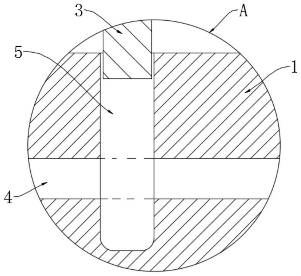
[0025]ReferenceFigure 1-4 , A formaldehyde treatment device suitable for narrow spaces, including a fixed housing 1, one side of the fixed housing 1 is provided with a circular cavity 2 and an elastic vibration plate 3 is installed in the middle of the circular cavity 2. The side wall of the hollow groove 2 is provided with a sliding groove 5 in the circumferential direction, and the edge of the elastic vibration plate 3 is slidingly connected with the sliding groove 5, and the bottom of the circular groove 2 is connected with an exhaust pipe 4, and the exhaust pipe 4 The end away from the circular cavity 2 is located outside the fixed housing 1, that is, the circular cavity 2 on the right side of the elastic diaphragm 3 communicates with the outside through the exhaust pipe 4 (withfigure 1 As an example), a sealing groove 7 is opened in the fixed shell 1, and the sealing groove body 7 contains adsorption purification substances, such as activated carbon, porous ore, etc., and the u...

Embodiment 2

[0035]ReferenceFigure 5-7The difference between this embodiment and embodiment 1 is that: the elastic vibrating plate 3 is a hollow structure, and the side of the elastic vibrating plate 3 away from the sealing groove 7 is symmetrically provided with a plurality of water-permeable holes 11, and a thin Tube 10, one end of the thin tube 10 is located below the chute 5 and is provided with a blocking block 13, the other end of the thin tube 10 penetrates the fixed housing 1 and extends to the outside of the fixed housing 1, and the elastic vibration plate 3 is provided with elastic The upper end of the elastic water absorbing strip 12 is fixedly connected to the upper end of the elastic vibrating plate 3, and the lower end of the elastic water absorbing strip 12 sequentially penetrates the elastic vibrating plate 3, the slide groove 5 and the blocking block 13 and extends into the thin tube 10, and is elastic The connection between the water absorbing strip 12 and the bottom of the ela...


PUM


Abstract

The invention discloses a formaldehyde treatment device suitable for a narrow space. The formaldehyde treatment device comprises a fixed shell, wherein a circular empty groove is formed in one side ofthe fixed shell, and an elastic vibration sheet is arranged in the middle portion of the circular empty groove; a sliding groove is formed in the side wall of the circular empty groove in the circumferential direction, and the edge of the elastic vibration sheet is connected with the sliding groove in a sliding mode; the bottom of the circular empty groove communicates with an exhaust pipe, and the end, far away from the circular empty groove, of the exhaust pipe is located outside the fixed shell; and a sealing groove is formed in the fixed shell, the upper end of the sealing groove communicates with the circular empty groove through a gas collecting pipe, and a plurality of gas collecting openings are formed in the side, far away from the circular empty groove, of the sealing groove. According to the formaldehyde treatment device suitable for the narrow space, air in the indoor narrow space can be pumped out under the action of sound waves or airflow, so that circulation of the indoor air and removal of harmful substances such as formaldehyde are accelerated, and the indoor air purification efficiency is improved.

Description

Technical field[0001]The present invention relates to the technical field of air purification, in particular to a formaldehyde treatment device suitable for narrow spaces.Background technique[0002]In the process of house decoration, it is inevitable to use artificial boards, paints, textiles and other materials. These materials are direct sources of harmful substances such as formaldehyde. Therefore, after the house decoration is completed, it takes a long time to ventilate and diffuse the smell before living. .[0003]When opening windows for ventilation, the wind speed in the open area is relatively high, which can quickly take away the polluted gas. For narrow spaces, it is difficult for the airflow to flow in large amounts. The formaldehyde released by the decoration materials will slowly accumulate and gradually escape to the surrounding environment. The effect of purifying indoor air by natural wind alone is poor. For this reason, some homeowners will ask professionals to remove...

Claims


Application Information

Patent Timeline
Patent Type & Authority Applications(China)
IPC IPC(8): F24F7/003F24F7/007F24F13/00F24F8/00B01D53/00B01D53/26F24F110/66
CPCB01D53/00B01D53/261B01D2257/708B01D2258/06F24F3/16F24F7/00F24F7/007F24F13/00F24F2007/005F24F2110/66
Inventor 沈超锋
Owner HUZHOU YUEBIN INTELLIGENT TECH CO LTD
Why Eureka
Try Eureka