Wind power blade

A technology of wind power blades and blade bodies, applied in the field of wind power blades, can solve the problems of poor flexibility, difficult processing, inconvenient disassembly and replacement of embedded bolts, etc., and achieve the effect of flexible use

Active Publication Date: 2021-02-05
上海玻璃钢研究院东台有限公司
View PDF5 Cites 0 Cited by
  • Summary
  • Abstract
  • Description
  • Claims
  • Application Information

AI Technical Summary

Problems solved by technology

However, the existing pre-embedded bolts are usually poured and fixed in the blade root, and since the pre-embedded bolts cannot be adjusted in the radial direction, when the diameter enclosed by the threaded holes on the main engine and the diameter enclosed by the pre-embedded bolts cannot Matching, it will not be installed, which brings difficulty to the processing, the accuracy of the position must be ensured, otherwise it cannot be installed, which makes the assembly flexibility poor, processing difficult, and the removal and replacement of embedded bolts is inconvenient

Method used


Image

  • Wind power blade
  • Wind power blade
  • Wind power blade

Examples


Embodiment Construction

[0021] The content of the present invention will be further described in detail below in conjunction with the accompanying drawings.

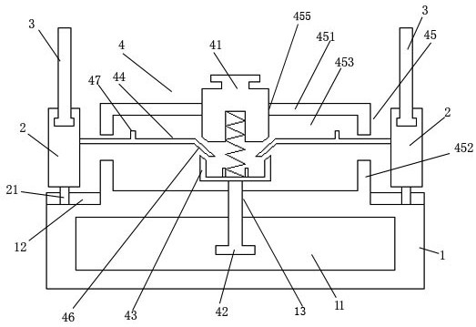
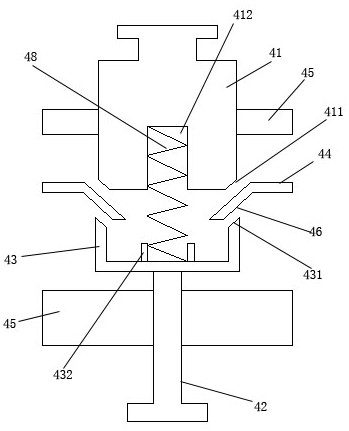
[0022] Such as Figures 1 to 5 As shown, a wind power blade includes a blade body, a blade root block 1, a radial floating mechanism 4, a radial sliding block 2, and a pre-embedded bolt 3; the root of the blade body is installed with a blade root block 1; the blade root The block 1 has a circular block structure; the inside of the blade root block 1 is provided with a driving cavity 11; the middle of the upper end of the driving cavity 11 is provided with a threaded channel 13; A plurality of sliding slots 12 radially distributed along the blade root block; a radial sliding block 2 is mounted on the sliding slots 12 for radial sliding engagement respectively; the upper ends of the radial sliding blocks 2 are respectively rotated and engaged A pre-embedded bolt 3 is installed; the radial floating mechanism 4 includes a driving chamber 45, a rad...


PUM


Abstract

The invention discloses a wind power blade. The wind power blade comprises a blade body, a blade root block, a radial floating mechanism, radial sliding blocks and embedded bolts. According to the wind power blade, inclined plates are clamped and installed between the upper driving ring surface of an upper driving threaded block and the lower driving ring surface of a lower driving ring sleeve, sothat the upper driving threaded block and the lower driving threaded rod synchronously rotate up and down to drive the multiple inclined plates to radially float towards the outer side or the inner side, and then the radial sliding blocks and the embedded bolts are driven to realize radial sliding, therefore, position adjustment is achieved, and use is more flexible.

Description

technical field [0001] The invention relates to a wind power blade. Background technique [0002] Wind power blades need to be connected to the main engine through blade root bolts. The connection methods mainly include T-shaped bolts and pre-embedded bolts. In the early days of the wind power industry, the power of the blades was small, and the load on the blade roots was small. The T-bolt method was simple in process and easy to control in quality. With the development of the times, the length and power of the blades have gradually increased, and the disadvantages of this connection method have also emerged. For example, due to the large distance between the blade root bolts, the number of blade root bolts is limited, and the load that the blade root can bear is low. Root cutting and punching produce more solid waste and the like. The pre-embedded bolt connection method can distribute more axial bolts under the same pitch circle diameter, so it can bear a larger load, an...

Claims


Application Information

Patent Timeline
IPC IPC(8): F03D1/06F03D13/10
CPCF03D1/0675F03D1/0658F03D13/10Y02E10/72
Inventor 吉玉峰夏保付姜益张平
Owner 上海玻璃钢研究院东台有限公司
Why Eureka
Try Eureka