Mold injection molding device special for new energy automobile interiors
A new energy vehicle and interior decoration technology, applied in packaging, transportation, packaging, containers, etc., can solve the problems of easy blockage of the hopper and adhesion of injected raw materials to the inner wall of the hopper, etc., achieve smooth circulation, increase deformation space, and improve elasticity Effect
- Summary
- Abstract
- Description
- Claims
- Application Information
AI Technical Summary
Problems solved by technology
Method used
Image
Examples
Embodiment 1
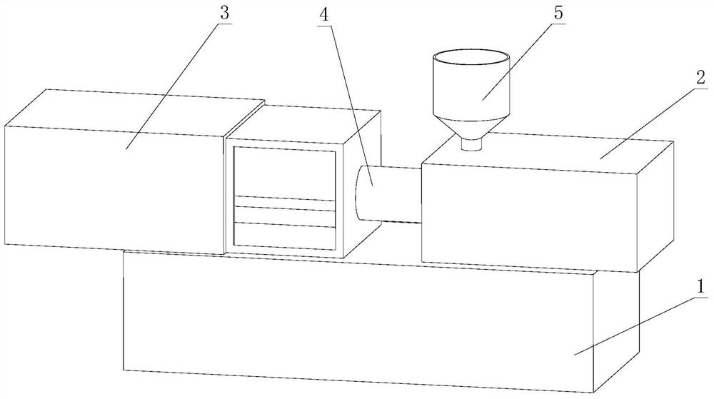
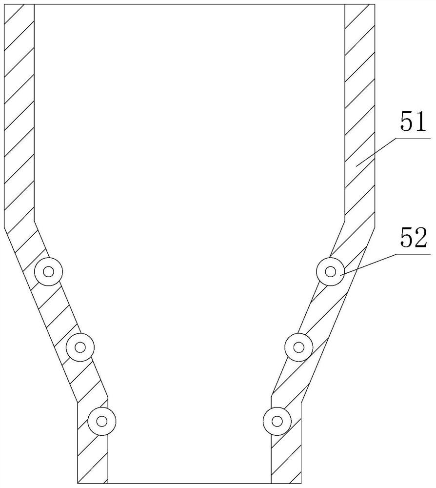
[0027] like figure 1 - image 3 As shown, the present invention provides a special mold injection molding device for new energy automobile interior decoration, including a base 1, and the left and right sides of the upper end of the base 1 are respectively provided with a mold structure 3 and a feed structure 2, and a mold structure 3 and a feed structure 2. A heating structure 4 is arranged between the material structures 2, a hopper 5 is arranged on the upper end of the feeding structure 2 close to the heating structure 4, and a hopper 51 is arranged inside the hopper 5, and the inner surface below the middle part of the hopper 51 is movably connected with an anti- Attachment structure 52 .
[0028] The inside of the anti-adhesion structure 52 is provided with a wind wheel 521. The inside of the wind wheel 521 is provided with an inner shock groove 522. The inner shock groove 522 is designed to be inclined. This design makes the wind wheel 521 rotate so that the vibration b...
Embodiment 2
[0031] As shown in the figure, on the basis of Embodiment 1, the present invention provides a technical solution: the interior of the wind wheel 521 is provided with an inner cavity 5212, and one side of the wind wheel 521 is provided with a vibration blocking rod 5211, and the vibration blocking rod 5211 It is integrated with the wind wheel 521. The side of the wind wheel 521 away from the vibration bar 5211 is hinged to a side vibration block 5214. The inside of the inner cavity 5212 is provided with a weight-adjusting shock ball 5213. Between the side shock block 5214 and the wind wheel 521 An elastic pull piece 5215 is fixedly connected between them, and the end of the side shock block 5214 is higher than the outer contour of the wind wheel 521. At the corner, the side vibration block 5214 can be moved and pulled back by the elastic pull piece 5215, so that the side vibration block 5214 hits the wind wheel 521, so as to separate the injection molding material adhered to the...
Embodiment 3
[0034] like Figure 5 As shown, on the basis of Embodiment 2, the present invention provides a technical solution: preferably, a cavity a1 is opened inside the side shock block 5214, and the middle part of the side shock block 5214 close to the wind wheel 521 is fixedly connected with Hemispherical rubber a4, there is an air groove a5 between the hemispherical rubber a4 and the side shock block 5214, and a shrapnel a2 is fixedly connected between the upper and lower ends of the cavity a1, and the shrapnel a2 is used to limit the shock ball a3. The shock ball a3 is fixedly connected.
[0035]In this embodiment, through the design of the hemispherical rubber a4 and the air groove a5, the side shock block 5214 can protect the wind wheel 521 and the side shock block 5214 when it hits the wind wheel 521, reducing the wear during collision. And through the air groove a5, the deformation space of the hemispherical rubber a4 is increased, thereby improving the elasticity of the hemis...
PUM
 Abstract
Description
Claims
Application Information
 - R&D
- Intellectual Property
- Life Sciences
- Materials
- Tech Scout
- Unparalleled Data Quality
- Higher Quality Content
- 60% Fewer Hallucinations
Browse by: Latest US Patents, China's latest patents, Technical Efficacy Thesaurus, Application Domain, Technology Topic, Popular Technical Reports.
© 2025 PatSnap. All rights reserved.Legal|Privacy policy|Modern Slavery Act Transparency Statement|Sitemap|About US| Contact US: help@patsnap.com


