Wheel cover for electric tool
A technology for electric tools and grinding wheel covers, which is applied in the field of grinding wheel covers, can solve problems such as troublesome replacement operations, and achieve the effect of suppressing shaking
- Summary
- Abstract
- Description
- Claims
- Application Information
AI Technical Summary
Problems solved by technology
Method used
Image
Examples
no. 1 Embodiment approach
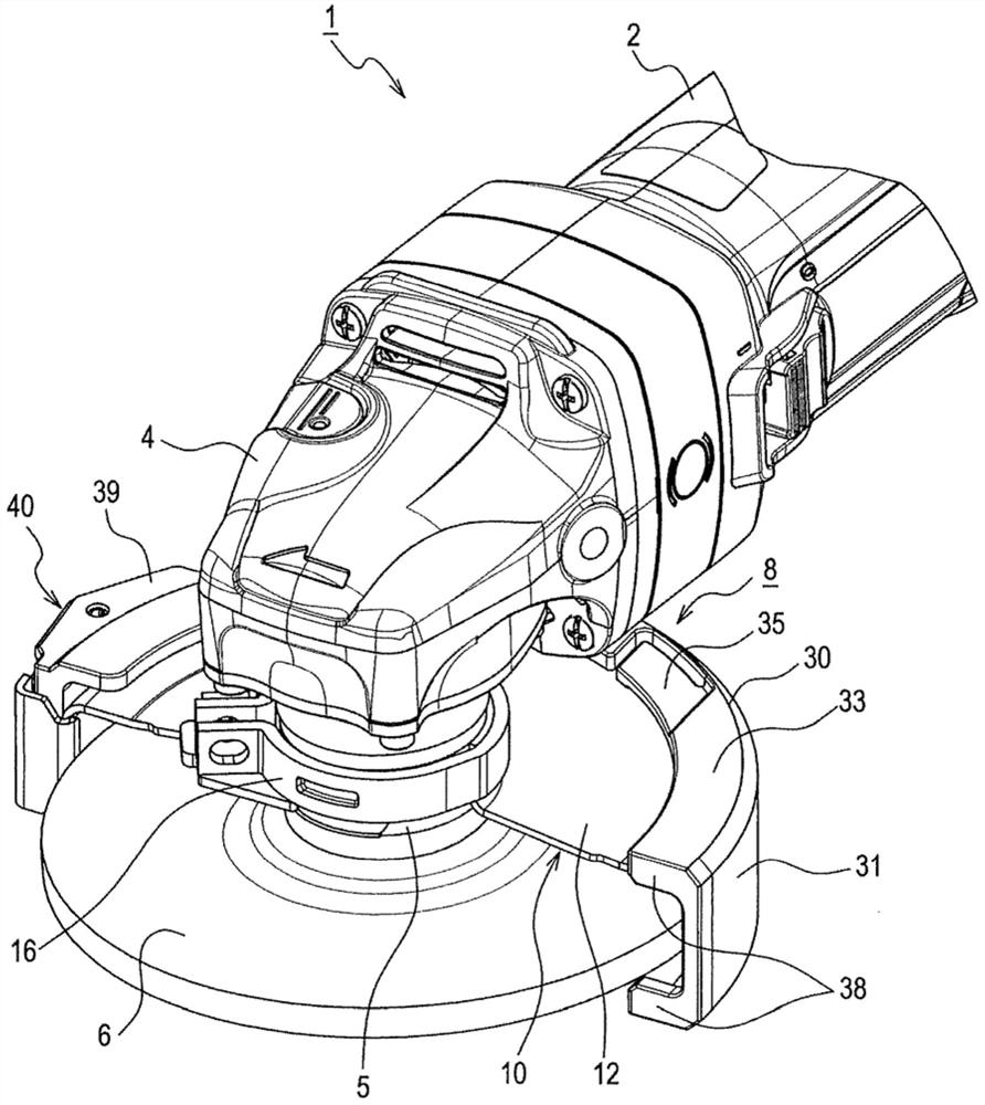
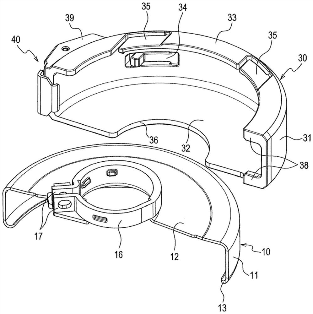
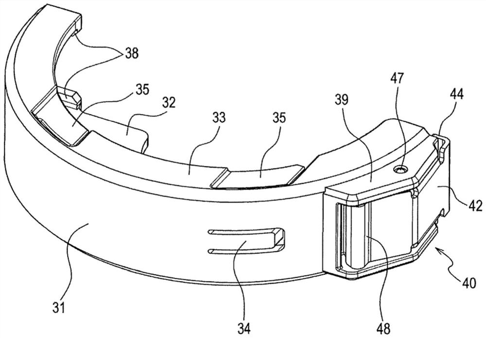
[0062] Such as figure 1 As shown, the grinder 1 of this embodiment is a hand-held electric tool (so-called disc grinder) for machining a workpiece by rotating a disc (disc)-shaped tip tool 6 . Here, machining includes grinding, lapping, cutting, and the like.
[0063] The grinding machine 1 has a motor housing 2 and a gear housing 4 as the housing of the main body of the grinding machine.
[0064] The motor case 2 is used to accommodate the motor, and is a substantially cylindrical case that can be held by the user. The rotation shaft of the motor protrudes toward the gear housing 4 disposed in front of the motor housing 2 .
[0065] In addition, a rear cover is provided on the opposite side of the gear case 4 , that is, behind the motor case 2 , and a drive circuit of the motor and the like are housed inside the rear cover.
[0066] The gear housing 4 is provided to close the front opening of the motor housing 2 . Inside the gear housing 4 is accommodated a gear mechanism...
no. 2 Embodiment approach
[0108] Next, the grinding wheel cover 8A of the second embodiment will be described.
[0109] The basic structure of the grindstone cover 8A of this embodiment is the same as that of the grindstone cover 8 of the first embodiment, but the structures of the second cover 30A and the engaging member 40A are different from those of the first embodiment. In the following description, this point of difference will be described. Regarding the second cover 30A and the engaging member 40A, the same drawing with the suffix A attached to the part corresponding to the first embodiment is described in the drawing. mark, and some descriptions are omitted.
[0110] In the grinding wheel cover 8A of this embodiment, like the first cover 10, the second cover 30A and the engaging member 40A are formed of metal plates.
[0111] Such as Figure 6 - As shown in FIG. 9 , a bent portion 38A is provided on one end side in the outer peripheral direction of the second outer peripheral protection port...
no. 3 Embodiment approach
[0129] Next, the grinding wheel cover 8B of the third embodiment will be described.
[0130] The basic structure of the grindstone cover 8B of this embodiment is the same as that of the grindstone cover 8 of 1st Embodiment, and the structure of the 2nd cover 30B and the engaging member 40B differs from 1st Embodiment. In the following description, this point of difference will be described. Regarding the second cover 30B and the engaging member 40B, the same drawing with the suffix B attached to the part corresponding to the first embodiment will be described. mark, and some descriptions are omitted.
[0131] In the grindstone cover 8B of this embodiment, like the grindstone cover 8A of the first embodiment, the second cover 30B and the engaging member 40B are formed of metal plates.
[0132] Such as Figure 10 ~ Figure 1 3, a bent portion 38B is provided on one end side in the outer peripheral direction of the second outer peripheral protection portion 31B, and an engaging ...
PUM
 Abstract
Description
Claims
Application Information
 - Generate Ideas
- Intellectual Property
- Life Sciences
- Materials
- Tech Scout
- Unparalleled Data Quality
- Higher Quality Content
- 60% Fewer Hallucinations
Browse by: Latest US Patents, China's latest patents, Technical Efficacy Thesaurus, Application Domain, Technology Topic, Popular Technical Reports.
© 2025 PatSnap. All rights reserved.Legal|Privacy policy|Modern Slavery Act Transparency Statement|Sitemap|About US| Contact US: help@patsnap.com


