Conveying clamp of passenger conveyer and conveying method of passenger conveyer
A technology for passenger conveyors and fixtures, used in transportation and packaging, escalators, etc., can solve problems such as damaged goods, collapse, and truss deformation, and achieve the effect of suppressing shaking and improving idle space.
- Summary
- Abstract
- Description
- Claims
- Application Information
AI Technical Summary
Problems solved by technology
Method used
Image
Examples
Embodiment approach 1
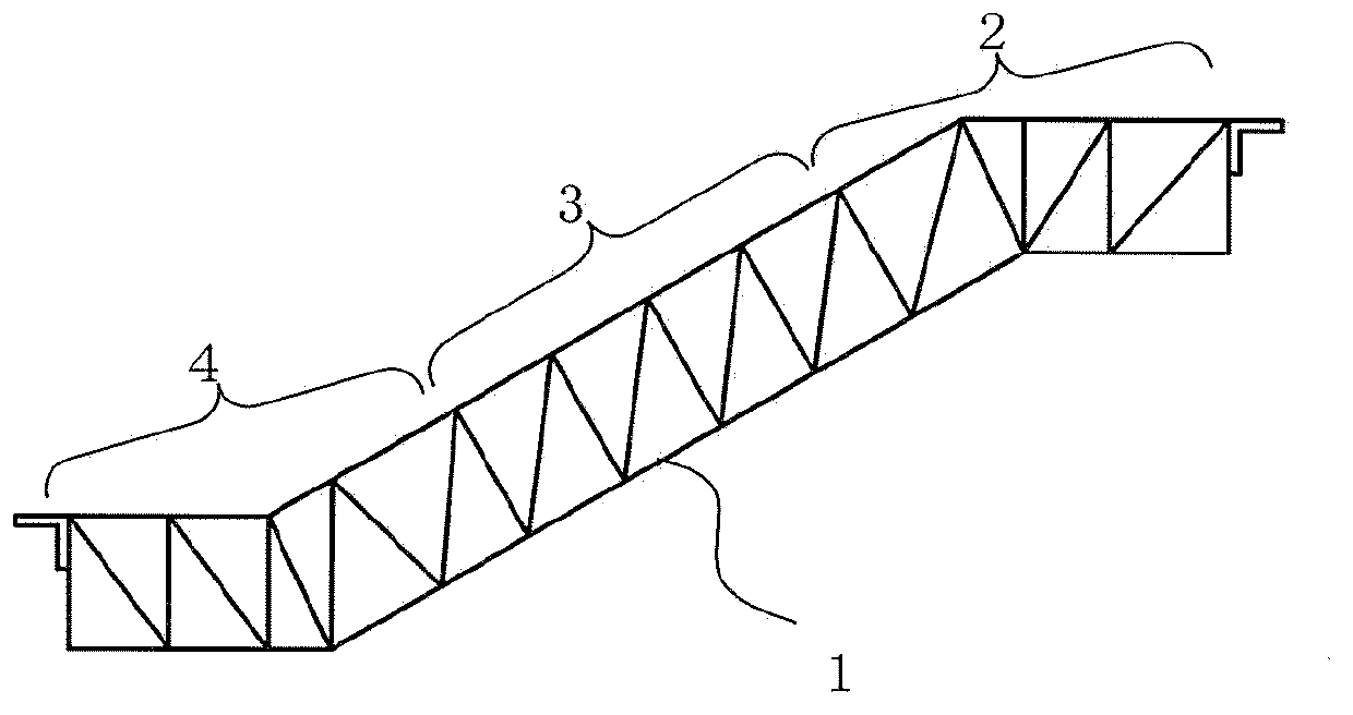
[0066] figure 1 It is a side view showing the entire truss of the passenger conveyor according to Embodiment 1 of the present invention. After the passenger conveyor 1 is manufactured in the factory, it is divided into an upper truss 2 composed of an upper horizontal part and a part of an inclined part and bent into a "く" shape; a straight middle truss 3 consisting of only an inclined part (because of The number of these parts increases or decreases due to the difference in story height), and the lower truss 4, which is composed of a part of the lower horizontal part and the inclined part and is bent into a "U" shape.
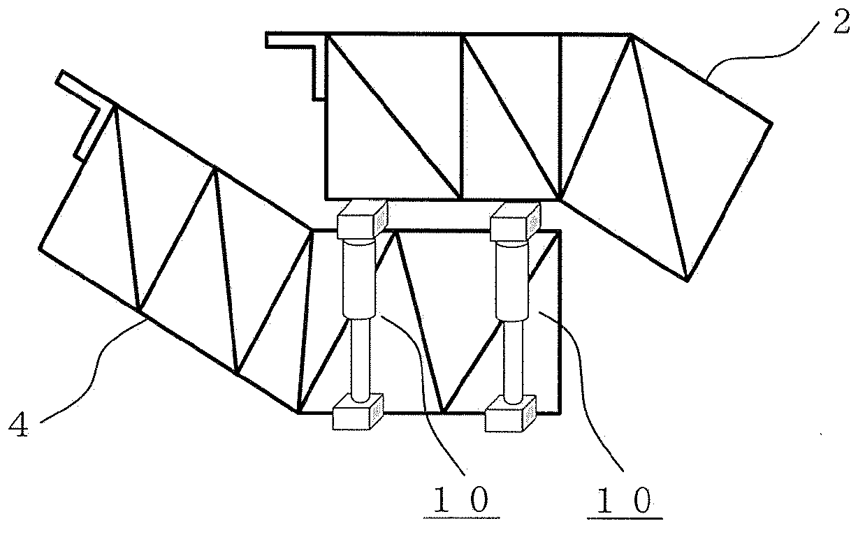
[0067] In the prior art, the divided trusses are loaded in a single form on containers, trucks, etc., or in the case of the upper truss, they are downloaded and placed on a supporting platform. After being transported to the installation site, the trusses are recombined and installed On the building.
[0068] Compared with the above-mentioned existing conveying met...
Embodiment approach 2
[0087] In the second embodiment, a case where a structure different from the support device 14 described in the previous first embodiment is used to fix the center beam 11 to a container, a truck, or the like will be described.
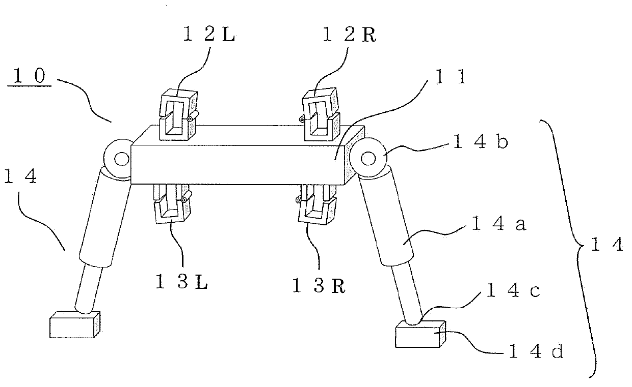
[0088] Figure 5 It is a schematic view seen from the front showing the conveyance jig of the passenger conveyor of Embodiment 2 of this invention. in Figure 5 Among them, the conveying jig 10 includes: a center beam 11; truss fixing members 12L, 12R, 13L, 13R provided above and below the center beam 11; hooks 15 provided at both ends of the center beam 11;
[0089] And the previous embodiment 1 figure 1 Compared with the structure of this embodiment 2, the Figure 5 The structure of is different in that it includes a hook 15 as a support portion instead of the support device 14. Therefore, the following description focuses on this different structure.
[0090] In this embodiment 2, there are Figure 5 The transport jig 10 of the structure connects the hoo...
Embodiment approach 3
[0094] In the third embodiment, a method of fixing to a container 21 corresponding to a cargo box using a transport jig 23 having a different structure from the transport jig 10 in the previous embodiments 1 and 2 will be described in detail.
[0095] First, the structure will be explained.
[0096] Image 6 It is a side view showing a state where the truss of the passenger conveyor is placed in a container using the transport jig of the passenger conveyor according to Embodiment 3 of the present invention. In addition, Figure 7 Is along Image 6 A cross-sectional view of line AA, which is a detailed cross-sectional view of a transport jig of a passenger conveyor according to Embodiment 3 of the present invention. In addition, Figure 8 It is a diagram showing the open state and the fixed state of the fixture for fixing the truss and the center beam used in the conveying jig of the passenger conveyor according to the third embodiment of the present invention. Figure 7 Detailed dr...
PUM
 Abstract
Description
Claims
Application Information
 - R&D Engineer
- R&D Manager
- IP Professional
- Industry Leading Data Capabilities
- Powerful AI technology
- Patent DNA Extraction
Browse by: Latest US Patents, China's latest patents, Technical Efficacy Thesaurus, Application Domain, Technology Topic, Popular Technical Reports.
© 2024 PatSnap. All rights reserved.Legal|Privacy policy|Modern Slavery Act Transparency Statement|Sitemap|About US| Contact US: help@patsnap.com


