A switched capacitor type DC/DC converter, switching power supply and control method
A technology of DC converters and switched capacitors, which is applied in the direction of converting DC power input to DC power output, adjusting electrical variables, and controlling/regulating systems. Volume, the effect of reducing the overall volume
- Summary
- Abstract
- Description
- Claims
- Application Information
AI Technical Summary
Problems solved by technology
Method used
Image
Examples
Embodiment 1
[0060] The switched capacitor DC / DC converter provided in this embodiment includes: a controllable switch and n switched capacitor modules; n is an integer greater than or equal to 1; when the DC / DC converter implements different voltage ratios, n can be Take different values, for example, when n=1, the voltage transformation ratio realized by the DC / DC converter is 2:1; when n=2, the voltage transformation ratio realized by the DC / DC converter is 2:1 ; When n=3, the voltage transformation ratio realized by the DC / DC converter is 5:1; when n=4, the voltage transformation ratio realized by the DC / DC converter is 8:1; when n=5 , the DC / DC converter achieves a voltage transformation ratio of 13:1, and so on.
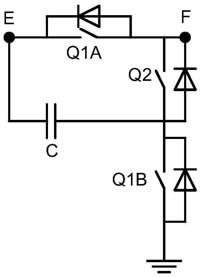
[0061] The n switched capacitor modules are connected in series to form a voltage transformation branch, and the voltage transformation branch is connected in series with the controllable switch. Each switched capacitor module has the same structure as Figure 3A As shown...
Embodiment 2
[0130] In order to suppress or reduce the inrush current that the capacitor in each switched capacitor module bears during charging, an inductor can be added to each switched capacitor module, specifically, it can be added at a position connected in series with the capacitor.
[0131] see Figure 14 , which is a schematic diagram of another switched capacitor DC / DC converter provided in the embodiment of the present application.
[0132] This embodiment provides another switched capacitor DC / DC converter. Figure 14 Taking n=4 as an example for introduction, this scheme is applicable to n being any integer.
[0133] In the switched capacitor DC / DC converter provided in this embodiment, each switched capacitor module further includes an inductor;
[0134] The inductor and the capacitor are connected in series to the first node and the second end of the second switch tube. Since the inductor has the ability to suppress sudden changes in current, such as Figure 14 As shown, ...
Embodiment 3
[0138] Figure 14 In the introduction, each switched capacitor module includes an inductor as an example. In order to reduce the overall volume of the converter and reduce costs, inductors can also be installed in some switched capacitor modules instead of each switched capacitor module. inductance.
[0139] see Figure 15 , which is a schematic diagram of another switched capacitor DC / DC converter provided in the embodiment of the present application.
[0140] In the converter provided in this embodiment, the way of setting the inductance is only applicable when n is an odd number. The inductor and the capacitor are connected in series to the first node and the second end of the second switch tube;
[0141] When the n is an odd number, start from the first end connected to the controllable switch, that is, sequentially number the switched capacitor modules from the high voltage side to the low voltage side, and number the switched capacitor modules with odd numbers in the ...
PUM
 Abstract
Description
Claims
Application Information
 - Generate Ideas
- Intellectual Property
- Life Sciences
- Materials
- Tech Scout
- Unparalleled Data Quality
- Higher Quality Content
- 60% Fewer Hallucinations
Browse by: Latest US Patents, China's latest patents, Technical Efficacy Thesaurus, Application Domain, Technology Topic, Popular Technical Reports.
© 2025 PatSnap. All rights reserved.Legal|Privacy policy|Modern Slavery Act Transparency Statement|Sitemap|About US| Contact US: help@patsnap.com


