
Clamp Circuit and Power Module

A clamping circuit and power module technology, which is applied to circuit devices, emergency protection circuit devices, output power conversion devices, etc. The effect of reducing the volume, reducing the resonance energy, and reducing the withstand voltage requirement

Active Publication Date: 2021-10-15
DELTA ELECTRONICS (SHANGHAI) CO LTD
View PDF6 Cites 0 Cited by
  • Summary
  • Abstract
  • Description
  • Claims
  • Application Information

AI Technical Summary

Problems solved by technology

[0006] The purpose of the present disclosure is to provide a clamping circuit and a power module using the clamping circuit, which are used to overcome the limitations and defects of related technologies at least to a certain extent due to the large volume of clamping circuit devices and poor clamping effect. Stability and other issues

Method used


Image

  • Clamp Circuit and Power Module
  • Clamp Circuit and Power Module
  • Clamp Circuit and Power Module

Examples


Embodiment Construction

[0039] Example embodiments will now be described more fully with reference to the accompanying drawings. Example embodiments may, however, be embodied in many forms and should not be construed as limited to the examples set forth herein; rather, these embodiments are provided so that this disclosure will be thorough and complete and will fully convey the concept of example embodiments to those skilled in the art. The described features, structures, or characteristics may be combined in any suitable manner in one or more embodiments. In the following description, numerous specific details are provided in order to give a thorough understanding of embodiments of the present disclosure. However, those skilled in the art will appreciate that the technical solutions of the present disclosure may be practiced without one or more of the specific details being omitted, or other methods, components, devices, steps, etc. may be adopted. In other instances, well-known technical solution...


PUM


Abstract

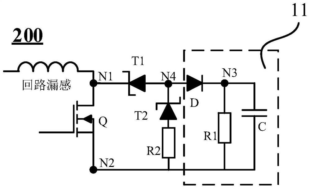
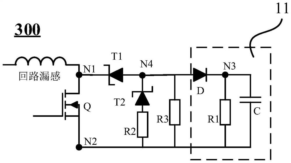
The present disclosure mainly provides a clamping circuit, which is coupled to the first end and the second end of the switch tube through the first node and the second node, including: an RCD loop, including a parallel connection between the second node and the third node The first resistor and the first capacitor between them, and the diode whose cathode is coupled to the third node; the first Zener diode, whose cathode is coupled to the first node, and whose anode is coupled to the anode of the diode at the first Four nodes. The embodiments of the present disclosure can improve the clamping reliability and clamping effect, and can reduce the volume and cost of the clamping circuit.

Description

technical field [0001] The present disclosure relates to the technical field of electronic circuits, in particular, to a clamping circuit and a power module using the clamping circuit. Background technique [0002] The clamping circuit is usually connected in parallel with the semiconductor switch, and absorbs the voltage spike generated by the leakage inductance current of the loop on the semiconductor switch when the semiconductor switch is turned off, so as to prevent the voltage at both ends of the semiconductor switch from being damaged by exceeding the withstand voltage of the semiconductor switch. Semiconductor switch tube. [0003] The clamping circuit in the related art is usually a capacitor clamping circuit or a resistor-capacitor-diode (RCD) clamping circuit. In the capacitor clamping circuit, the clamping capacitor needs to be selected according to the voltage of the switching tube to be clamped, and the volume of the capacitor is usually relatively large. Whe...

Claims


Application Information

Patent Timeline
Patent Type & Authority Patents(China)
IPC IPC(8): H02M1/32
CPCH02M1/32H03K17/133H03K17/165H02H9/04H03K17/08H02M1/34H02M1/44H02M3/156H02H3/20H02H7/09
Inventor 乔理峰李午英张德辉刘腾应建平
Owner DELTA ELECTRONICS (SHANGHAI) CO LTD
Learn More