A kind of cable laying engineering machinery
A technology for construction machinery and cable laying, applied in the direction of cable laying equipment, etc., can solve the problems of troublesome operation, unfavorable use, damaged cable sheath, etc., and achieve the effect of improving the effect and improving the accuracy.
- Summary
- Abstract
- Description
- Claims
- Application Information
AI Technical Summary
Problems solved by technology
Method used
Image

Examples
Embodiment 1
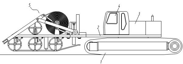
[0038] Such as figure 1 As shown, a cable laying engineering machine is provided, and the engineering machine includes a crawler belt 1, a rotating platform 2, a car body 3, and a cab 4, wherein the crawler belt 1 is used to support the walking of the engineering machinery, and the rotating platform 2 is mounted on the crawler belt 1 to support the vehicle body 3 and the cab 4. The control device for controlling the construction machinery is installed in the cab 4. The front of the vehicle body 3 is connected to the laying part 5 for laying cables. For the crawler belt in this embodiment, its main function is exactly to be used for walking, therefore it can be set as the wheel according to the different conditions of adaptation. The rotating platform 2 is mounted on the crawler, to be precise, it should be mounted on the bracket of the crawler. To simplify the description, it is directly written as being mounted on the crawler. The car body 3 is used to set the power unit and...
Embodiment 2
[0040] Such as figure 1 As shown, a cable laying engineering machine is provided, and the engineering machine includes a crawler belt 1, a rotating platform 2, a car body 3, and a cab 4, wherein the crawler belt 1 is used to support the walking of the engineering machinery, and the rotating platform 2. Mounted on the crawler belt 1 to support the car body 3 and the cab 4, the cab 4 is provided with a control device for controlling construction machinery, and the front of the car body 3 is detachably connected with a laying cable for laying Part 5. For the crawler belt in this embodiment, its main function is exactly to be used for walking, therefore it can be set as the wheel according to the different conditions of adaptation. The rotating platform 2 is mounted on the crawler, to be precise, it should be mounted on the bracket of the crawler. To simplify the description, it is directly written as being mounted on the crawler. The car body 3 is used to set the power unit and...
Embodiment 3
[0042] Such as figure 1 As shown, a cable laying engineering machine is provided, and the engineering machine includes a crawler belt 1, a rotating platform 2, a car body 3 and a cab 4, the crawler belt 1 is used to support the walking of the engineering machine, and the rotating platform 2 is used for The vehicle body 3 and the driver's cab 4 are equipped with a controller, an operating device, etc. inside the driver's cab 4 .
[0043] Depend on figure 1 It can be seen that the laying part 5 for laying cables is arranged in front of the rotating platform 2 .
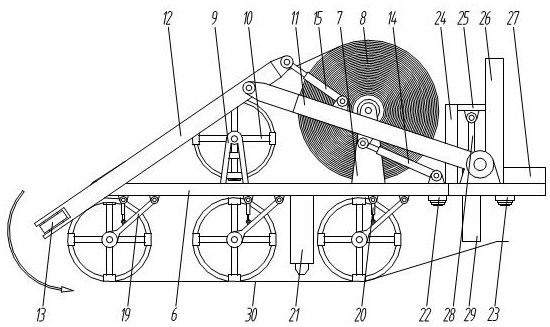
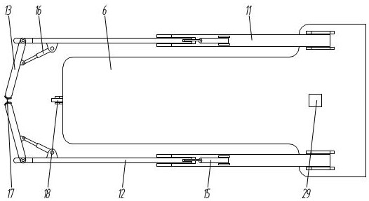
[0044] figure 2 Specifically shows the structure of laying part 5 in the present embodiment, as figure 2 , 3 As shown, the laying part 5 includes a laying platform 6, on which a first bracket 7 and a second bracket 9 are sequentially arranged from back to front, and the first bracket 7 is used to support the cable ring 8, so The cable coil 8 is replaceably arranged on the first bracket 7, which is convenient for ...
PUM
 Abstract
Description
Claims
Application Information
 - R&D
- Intellectual Property
- Life Sciences
- Materials
- Tech Scout
- Unparalleled Data Quality
- Higher Quality Content
- 60% Fewer Hallucinations
Browse by: Latest US Patents, China's latest patents, Technical Efficacy Thesaurus, Application Domain, Technology Topic, Popular Technical Reports.
© 2025 PatSnap. All rights reserved.Legal|Privacy policy|Modern Slavery Act Transparency Statement|Sitemap|About US| Contact US: help@patsnap.com