
Space debris orbit rapid evolution method

A space debris and orbit technology, applied in design optimization/simulation, special data processing applications, etc., can solve problems such as large computing costs, space debris orbit consumption, and a large number of debris, to ensure orbit accuracy, speed up orbit evolution, and reduce Computational Efficiency Effects

Pending Publication Date: 2021-02-02
NORTHWESTERN POLYTECHNICAL UNIV
View PDF0 Cites 0 Cited by
  • Summary
  • Abstract
  • Description
  • Claims
  • Application Information

AI Technical Summary

Problems solved by technology

However, space collisions and space disintegration accidents often produce a large number of debris
At the same time, the amount of existing space debris is very large
Therefore, the long-term evolution of space debris orbits requires a large computational cost
Furthermore, in addition to the gravitational force of the earth, the movement of space debris is also affected by complex perturbations such as the gravitational force of the moon, the sun, the solar light pressure, and the thin atmosphere, which further increases the complexity of calculations.

Method used


Image

  • Space debris orbit rapid evolution method
  • Space debris orbit rapid evolution method
  • Space debris orbit rapid evolution method

Examples


Embodiment 1

[0050] A high-efficiency space debris orbit rapid evolution method, the orbit evolution of the method is divided into the following five steps:

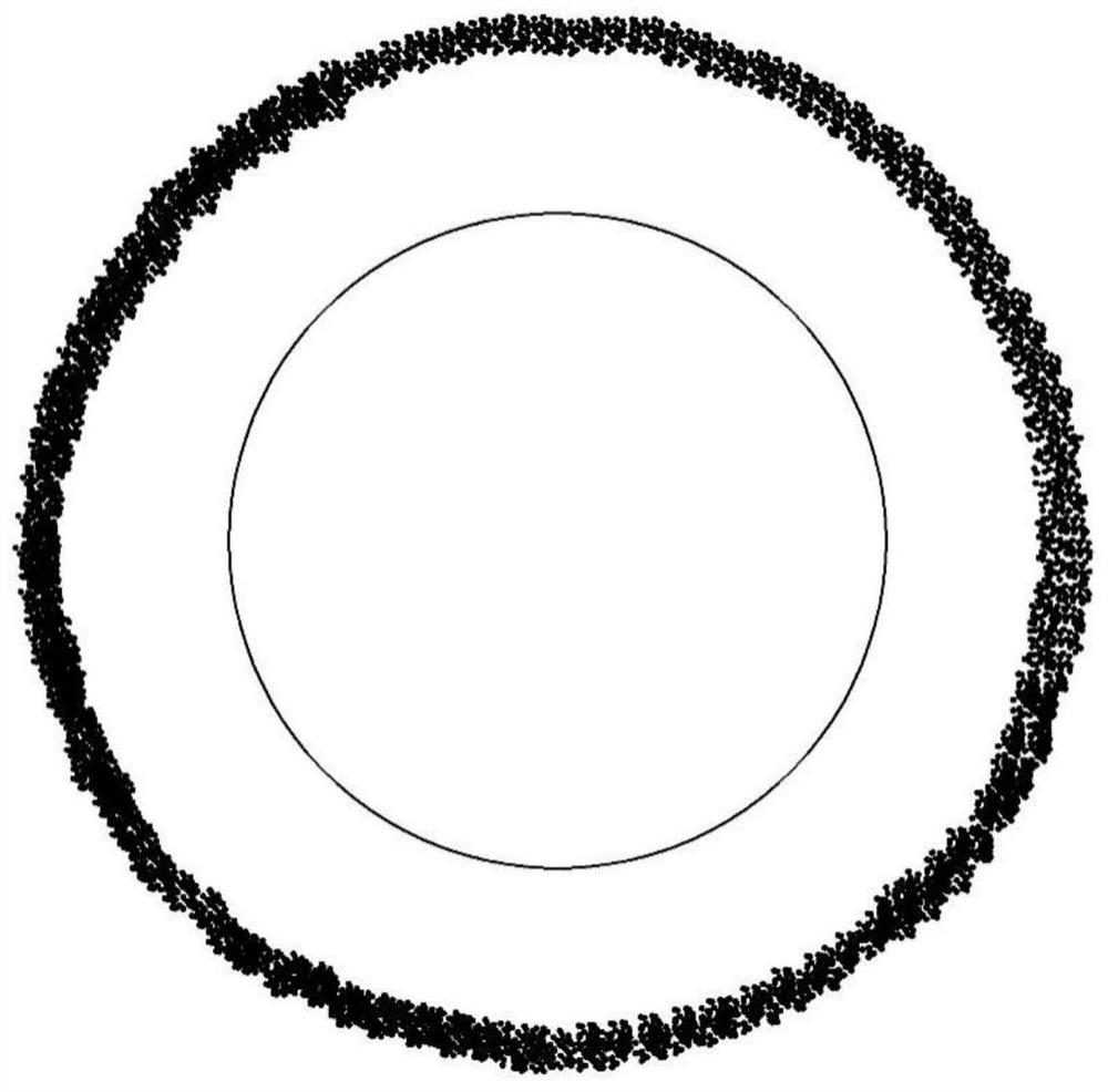
[0051] Step 1. Use the space disintegration model of NASA to simulate the space disintegration of a certain spacecraft, and obtain a series of fragments of different sizes, as well as the corresponding area-to-mass ratio, mass and velocity increment (produced by disintegration).

[0052] The amount of debris produced by disintegrating the model is determined by formula (1):

[0053] N(L c ) = S6L c -1.6 (1)

[0054] Among them, L c is the characteristic length, S is a parameter, determined according to the disintegration model.

[0055] Then the surface-to-mass ratio of each fragment is determined by the binormal distribution (2):

[0056]

[0057] Among them, γAlg (η), η=A / M; θAlg (L c ); ε(θ) is the weight coefficient, which is determined by different disintegration types. mu i and σ i are the mean and variance of the...

Embodiment 2

[0077] Step 1, establishing the gravitational field model at the center of the earth and the dynamics model in the case of perturbation of space debris;

[0078] Step 2, constructing the computer algorithm and polynomial integral algorithm of Taylor polynomial automatic approximation;

[0079] Step 3, describe the initial velocity increment of the space debris in polynomial form, and perform Taylor polynomial approximation on the vector field of the ordinary differential equation describing the motion law of the space debris;

[0080] Step 4: Using the polynomial integration method, the polynomial differential equation obtained in step 3 is integrated along time to obtain a polynomial state solution at a certain moment. It is worth noting that the approximation error of this solution depends on the order of the Taylor expansion order, the size of the initial velocity increment and the time length of the orbital evolution;

[0081] Step 5. Substitute the velocity increments of...


PUM


Abstract

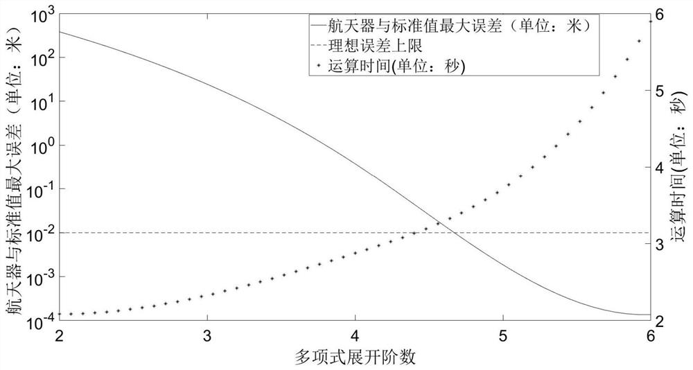
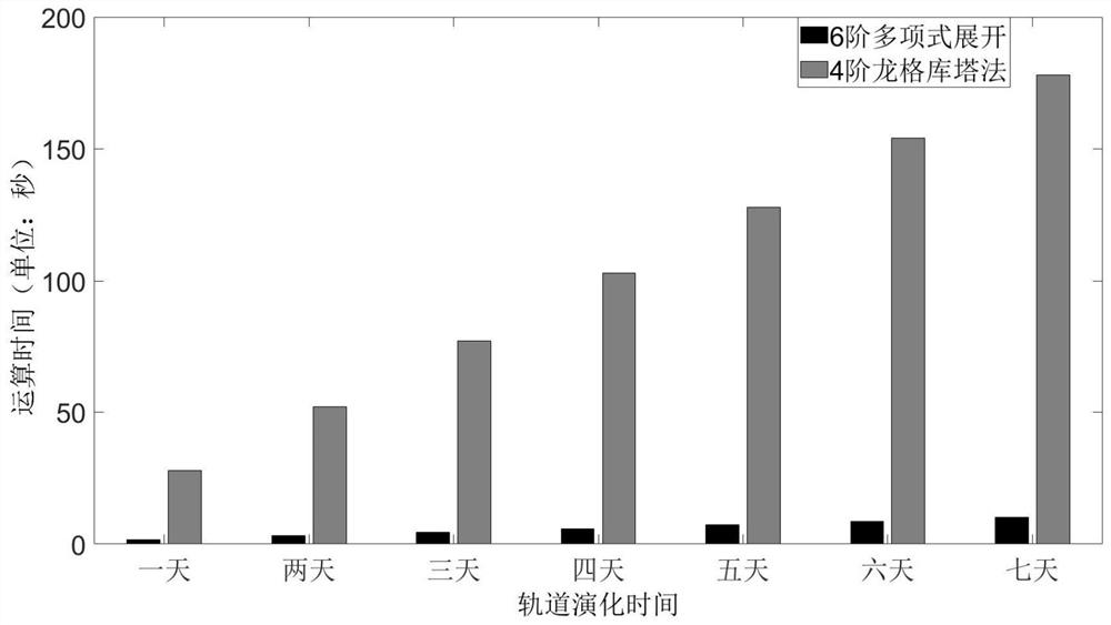
The invention discloses a space debris orbit rapid evolution method, and belongs to the field of spacecraft orbit prediction. The states of a plurality of fragments are described as a nominal state and a corresponding state deviation distribution form through a Taylor polynomial, and polynomial integration is used for replacing a large number of repeated fragment orbital integral operations. A large amount of fragment evolution is changed into a numerical value with an extremely high speed to be brought into the process, the overall calculation efficiency is greatly reduced, and the acceleration effect of several orders of magnitudes can be achieved. By adopting high-order Taylor expansion, the operation precision of the technical scheme provided by the invention can theoretically reach the precision the same as that of the traditional Monte Carlo targeting method. By balancing the calculation precision and the calculation efficiency, the error of the five-order approximation method issmaller than 0.01 m, and the situation that large precision is sacrificed due to accelerated operation is effectively avoided. According to the method, a large number of space debris orbits can be rapidly evolved, the orbital evolution speed of a large number of debris is greatly increased, and the orbital precision in the whole evolution process can be guaranteed.

Description

technical field [0001] The invention belongs to the field of orbit forecasting of spacecraft, and relates to a method for rapid evolution of orbits of space debris. Background technique [0002] With the continuous development of aerospace technology, the number of artificial satellites and space debris has increased significantly. The risks of on-orbit collision and self-disintegration of space objects have seriously affected normal space activities. If an accidental explosion or collision occurs, more space debris will be produced, which will further aggravate the deterioration of the space environment. Therefore, in recent years, experts in the aerospace field believe that it is not enough to slow down the formation of space debris. Even if future space activities do not produce new space debris, existing space debris and satellites will still face a huge threat of collision. Therefore, it is necessary to clear the existing space debris, and accurately predicting the tr...

Claims


Application Information

Patent Timeline
Patent Type & Authority Applications(China)
IPC IPC(8): G06F30/20
CPCG06F30/20
Inventor 孙冲陈建林张震袁源
Owner NORTHWESTERN POLYTECHNICAL UNIV
Learn More