
Lens and structured light projection module

A lens and light source technology, applied in optics, optical components, instruments, etc., can solve the problems of high cost and complex structure of collimating mirrors and diffractive optical components, and achieve the goal of reducing manufacturing cost, simplifying structure, and achieving a large field of view. Effect

Pending Publication Date: 2021-02-02
DONGGUAN VISIONX-TECH CO LTD
View PDF0 Cites 3 Cited by
  • Summary
  • Abstract
  • Description
  • Claims
  • Application Information

AI Technical Summary

Problems solved by technology

[0004] The purpose of the present invention is to provide a lens and a structured light projection module to solve the problem of using a collimator and a diffractive optical element in obtaining depth information in the existing structured light module. Taller and more complex questions

Method used


Image

  • Lens and structured light projection module
  • Lens and structured light projection module
  • Lens and structured light projection module

Examples


Embodiment Construction

[0027] In order to make the purpose, technical solutions and advantages of the embodiments of the present invention clearer, the technical solutions in the embodiments of the present invention will be clearly and completely described below in conjunction with the drawings in the embodiments of the present invention. Obviously, the described embodiments It is a part of embodiments of the present invention, but not all embodiments. The components of the embodiments of the invention generally described and illustrated in the figures herein may be arranged and designed in a variety of different configurations.

[0028] Accordingly, the following detailed description of the embodiments of the invention provided in the accompanying drawings is not intended to limit the scope of the claimed invention, but merely represents selected embodiments of the invention. It should be noted that, in the case of no conflict, various features in the embodiments of the present invention can be com...


PUM


Abstract

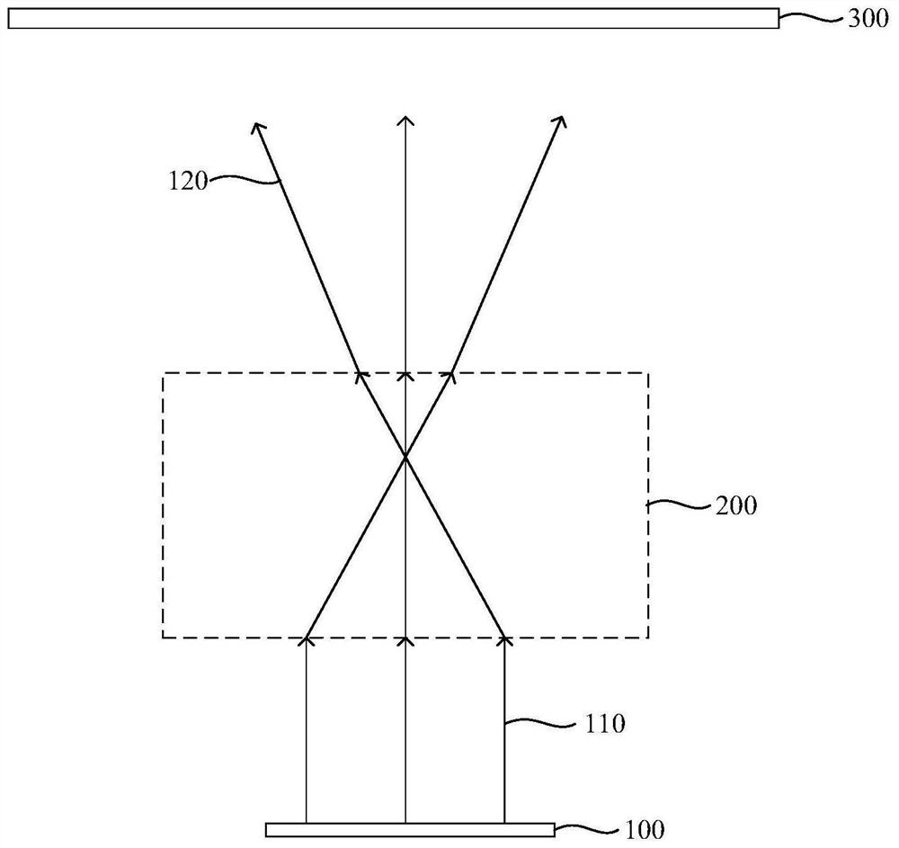
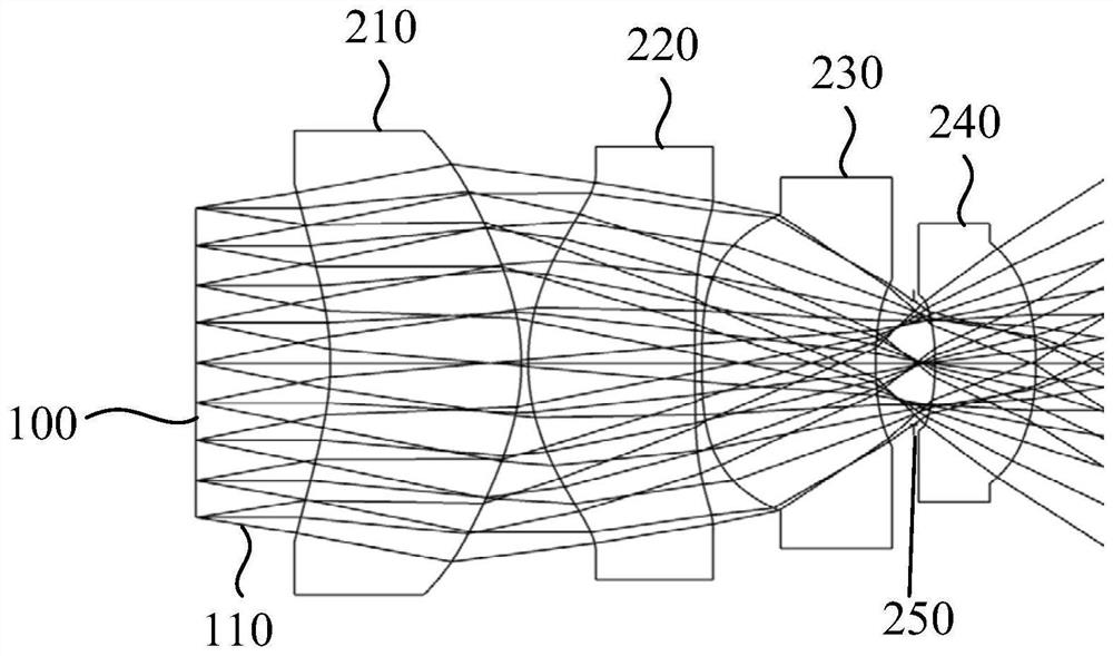
The invention provides a lens and a structured light projection module, and relates to the technical field of optical devices. The lens comprises a first convergent lens, a second convergent lens, a third convergent lens and a fourth convergent lens which are sequentially arranged along a light emitting direction, wherein the first convergent lens, the second convergent lens, the third convergentlens and the fourth convergent lens are all aspheric lenses. Under the action of the converging lens, the divergent light beams are finally intersected on the main optical axis to form a certain included angle to be projected into a target area in the form of parallel light beams, so that a light spot group is formed, and the depth information of an object in the target area is measured. When depth information is measured in some scenes, the requirement for the number of light spots is not high, therefore a diffractive optical element can be prevented from being used, the manufacturing cost ofthe lens is effectively reduced, the structure of the lens is simplified, and the assembling difficulty is also reduced. Through the lens, the distance between adjacent light spots can be increased,and therefore a larger field angle is formed.

Description

technical field [0001] The invention relates to the technical field of optical devices, in particular to a lens and a structured light projection module. Background technique [0002] Two-dimensional imaging devices can obtain two-dimensional plane information of objects. Due to the rapid improvement of people's living standards, traditional two-dimensional imaging devices have gradually been unable to meet people's daily needs. With the in-depth research of science and technology, on the basis of two-dimensional imaging, the three-dimensional imaging device can further obtain the depth information of the object, thereby constructing a three-dimensional three-dimensional model. [0003] In the 3D imaging device, the core component is the structured light emission module, which mainly projects the spot array to the target space through the collimating mirror and the diffraction element during projection, and uses the time-of-flight ranging to obtain the depth information of t...

Claims


Application Information

Patent Timeline
Patent Type & Authority Applications(China)
IPC IPC(8): G02B13/00G02B13/18
CPCG02B13/00G02B13/18
Inventor 郝春艳戴书麟刘风雷彭天才
Owner DONGGUAN VISIONX-TECH CO LTD
Learn More