
Anti-logic proportional valve and vane pump variable control system

A proportional valve and inverse logic technology, applied in the direction of pump control, lubricating oil control valve, sliding valve, etc., can solve problems such as complex structure, and achieve the effect of simple structure installation, good stability, and easy guarantee of hole precision

Pending Publication Date: 2021-02-02
HUNAN OIL PUMP
View PDF0 Cites 1 Cited by
  • Summary
  • Abstract
  • Description
  • Claims
  • Application Information

AI Technical Summary

Problems solved by technology

[0006] Aiming at the defects of the complex structure of the existing control system, a variable control system of the vane pump is proposed. The structure of the control system is simple to install, and the structure of the valve control is regular, which is beneficial to ensure the stability of the output pressure of the vane pump.

Method used


Image

  • Anti-logic proportional valve and vane pump variable control system
  • Anti-logic proportional valve and vane pump variable control system
  • Anti-logic proportional valve and vane pump variable control system

Examples


Embodiment 1

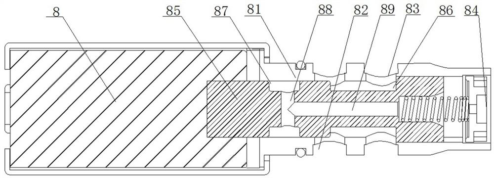
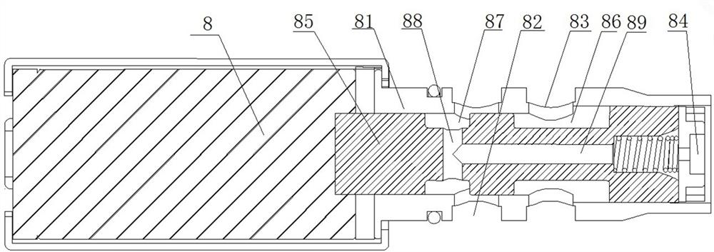
[0032] like figure 1 , 2 As shown, an inverse logic proportional valve, the inverse logic proportional valve 8 includes a valve body 81, a plunger 85 and a spring, the valve body 81 is provided with a valve hole for accommodating the plunger 85 and the spring, and the valve body 85 is provided with a communicating valve hole A port 82, P port 83 and T port 84; the outer peripheral surface of the plunger 85 is provided with a first annular oil groove 86, the first annular oil groove 86 can make the A port 82 and P port 83 intercommunication; the cross-sectional area of ​​the groove wall of the first annular oil groove 86 close to the spring is larger than the cross-sectional area of ​​the other side, thereby forming an area difference; a second annular oil groove 87 is also provided on the plunger 85 of the first annular oil groove 86 away from the spring , the second annular oil groove 87 can communicate with port A 82 in the open state of the inverse logic proportional valve...

Embodiment 2

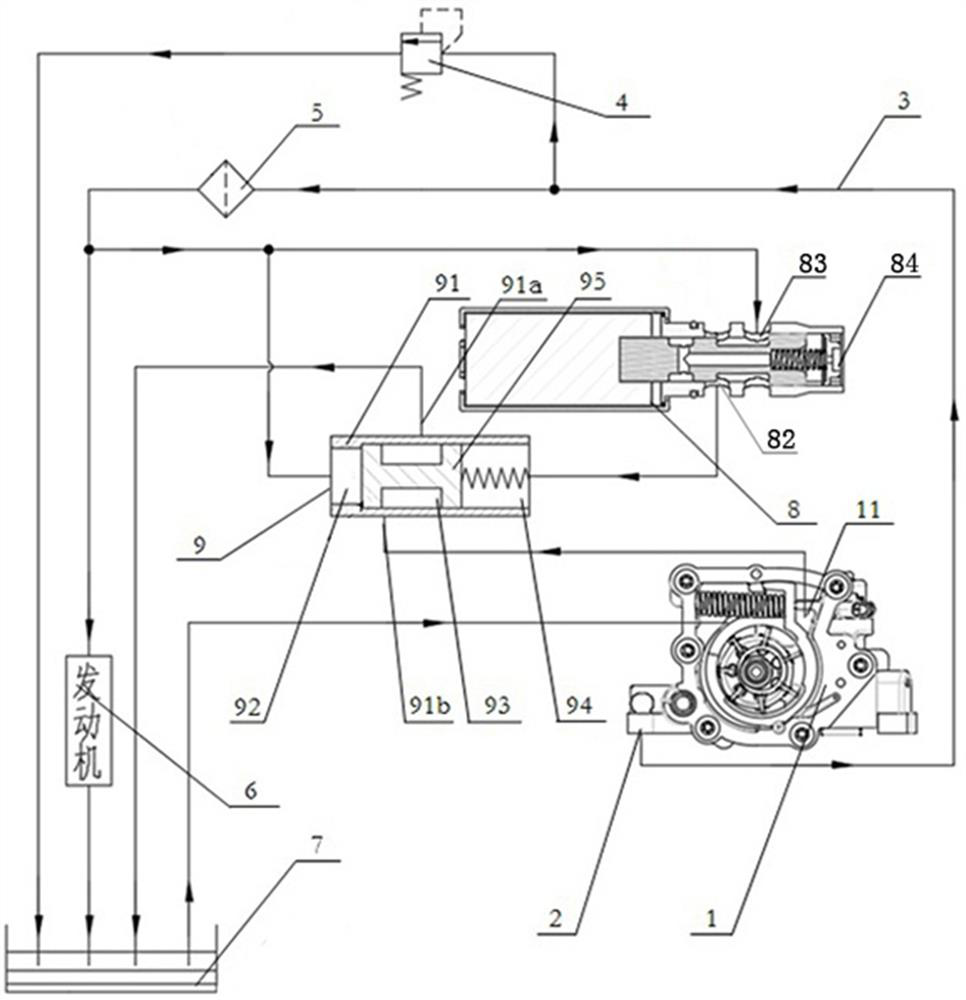
[0034] like Figures 1 to 4 As shown, a vane pump variable control system includes a vane pump 1, an oil outlet 2, a main oil passage 3, an oil pan 7 and a mechanical valve 9. The vane pump 1 includes a pump body, a feedback pressure oil chamber 11, a rotor and Variable slider; the control system also includes an inverse logic proportional valve 8, the inverse logic proportional valve 8 includes a valve body 81, a plunger 85 and a spring, the valve body 81 is provided with a valve hole for accommodating the plunger 85 and the spring, and the valve body 85 is set There are A port 82, P port 83 and T port 84 communicating with the valve hole; the outer peripheral surface of the plunger 85 is provided with a first annular oil groove 86, and the first annular oil groove 86 can make the A port 82 communicates with P port 83; the cross-sectional area of ​​the groove wall of the first annular oil groove 86 close to the spring is larger than the cross-sectional area of ​​the other sid...


PUM


Abstract

The invention discloses an anti-logic proportional valve and a vane pump variable control system, and relates to the technical field of automobile oil pump displacement control. The anti-logic proportional valve comprises a valve body, a plunger and a spring; a valve hole for accommodating the plunger and the spring is formed in the valve body; the valve body is provided with a port A, a port P and a port T which communicate with the valve hole; a first annular oil groove and a second annular oil groove are formed in the peripheral surface of the plunger; a radial hole communicating with the second annular oil groove is further formed in the plunger; and an axial hole connected with the radial hole and the T port is further formed in the middle of the plunger. The precision of the valve body hole of the proportional valve is easy to guarantee. The invention further relates to a vane pump variable control system using the anti-logic proportional valve. The control system is simple in structure installation, the mechanical valve control structure is regular, and the stability of output pressure of a vane pump is facilitated.

Description

technical field [0001] The invention relates to the technical field of displacement control of automobile oil pumps, in particular to a variable control system of an inverse logic proportional valve and a vane pump. Background technique [0002] Since the operation of the automobile engine oil pump also consumes part of the engine power, the traditional fixed-displacement oil pump is designed according to the demand of the engine oil pump when the engine is hot and idling. Many, when the speed of the engine rises to a certain level, the output flow of the oil pump will be greater than the demand of the engine, and the oil pump pressure limiting valve must be used to bypass the excess oil, resulting in a waste of energy; to reduce the oil pump For power consumption, it is necessary to match the oil supply of the oil pump with the actual oil demand of the engine, and the oil pump with variable displacement control can meet this requirement. [0003] The Chinese Utility Model ...

Claims


Application Information

Patent Timeline
IPC IPC(8): F16K11/07F16K3/314F16K17/30F16K31/122F16K27/04F16N23/00F04C14/24F04C14/12F01M1/02
CPCF01M1/02F04C14/12F04C14/24F16K3/314F16K11/0716F16K17/30F16K27/041F16K31/1221F16N23/00
Inventor 汤晓磊许仲秋刘光明佘笑梅
Owner HUNAN OIL PUMP
Learn More