
Special tooling for hoisting high-pressure heaters in thermal power plants and using methods thereof

A technology for high-pressure heaters and thermal power plants, which is applied in transportation and packaging, load suspension components, etc., and can solve the problems of insufficient space for high-pressure heaters in place, limited lifting height of high-pressure heaters, and broken wires of steel wire ropes. and other issues, to achieve the effect of ensuring safety and stability, low cost, and reasonable stress on tooling

Active Publication Date: 2022-04-12
POWERCHINA SEPCO1 ELECTRIC POWER CONSTR CO LTD
View PDF7 Cites 0 Cited by
  • Summary
  • Abstract
  • Description
  • Claims
  • Application Information

AI Technical Summary

Problems solved by technology

[0004] Method 1: Use the hook sets that come with the two lifting beams as the bearing points, install two steel wire ropes on each hook set, and connect the steel wire ropes of the two lifting beams to the temporary lifting lugs on the upper and lower parts of the high-pressure heater respectively However, the original hook assembly is used to install the steel wire rope. The steel wire rope is at a certain angle to the horizontal direction. During the rotation process after lifting, the steel wire rope will contact the head of the high-pressure heater. The inner side of the lifting lug has serious friction. If the length of the wire rope is increased, although the frictional contact between the wire rope and the head of the high-pressure heater can be alleviated, the lifting height of the high-pressure heater is obviously limited, and the seating height of the vertical high-pressure heater in a narrow space cannot be solved. The problem of insufficient space;
[0005] Method 2: Remove the hook group attached to the lifting beam, set up two special steel wire ropes on the upper part of the lifting beam, and use the upper part of the lifting beam as a bearing point. However, by setting up two special steel wire ropes on the upper part of the lifting beam, the upper part of the lifting beam is used as a load-bearing point. There is a sliding tendency on the lifting beam, and the friction force between the wire rope and the lifting beam will also cause the lifting beam to tilt in the vertical direction, which has a direct impact on the force of the tooling, and there is a safety risk;
[0006] Method 3: re-arrange two lifting points at the lower part of the lifting beam, install two special wire rope slings, and use the lower part of the lifting beam as a bearing point, and connect the steel wire ropes of the two lifting beams to the temporary lifting lugs on the upper and lower parts of the high-pressure heater respectively However, the hoisting point is arranged at the lower part of the lifting beam, and a special wire rope sling is installed. During the rotation process after hoisting, the steel wire rope and the temporary lifting lug of the high-pressure heater are subjected to rigid friction on the circumference, and the steel wire of the wire rope has the hidden danger of wear and tear. The device itself is not good

Method used


Image

  • Special tooling for hoisting high-pressure heaters in thermal power plants and using methods thereof
  • Special tooling for hoisting high-pressure heaters in thermal power plants and using methods thereof
  • Special tooling for hoisting high-pressure heaters in thermal power plants and using methods thereof

Examples


Embodiment

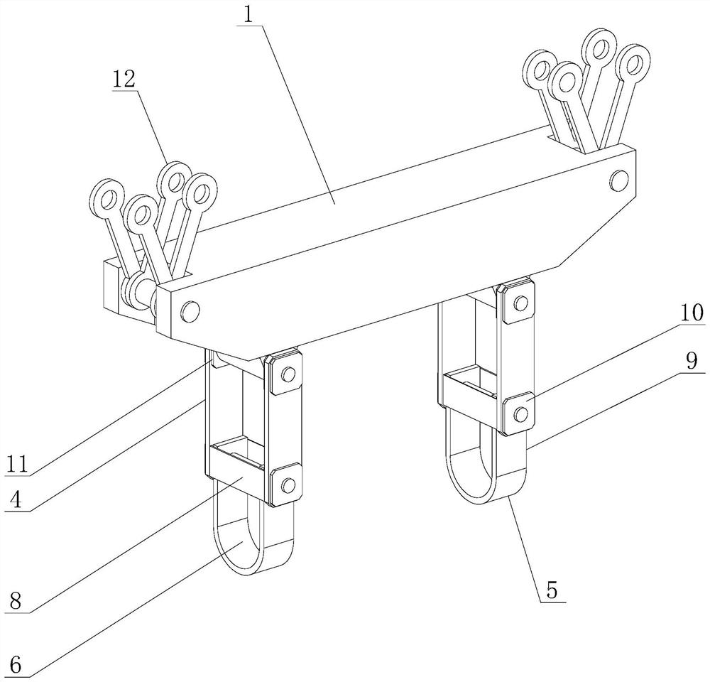
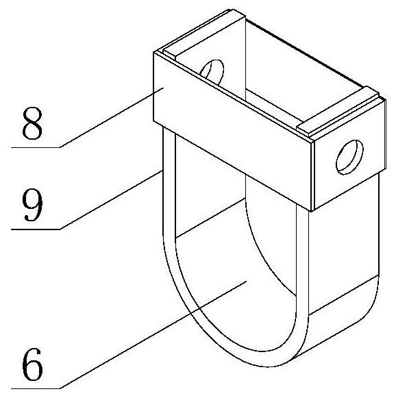
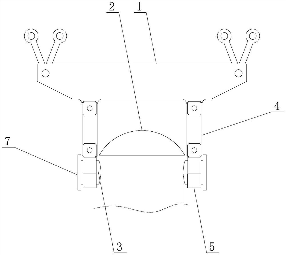
[0033] Example: as attached Figure 1-3 As shown, the present invention is a special tool for hoisting a high-pressure heater in a thermal power plant, including a lifting beam 1, a temporary lifting lug 3 fixed on a high-pressure heater 2, and the number of temporary lifting lugs 3 is four, two Each is a group, and a group of temporary lifting lugs 3 are welded on the outer walls of the upper and lower ends of the high pressure heater 2 . The bottom of the lifting beam 1 is symmetrically provided with two downwardly extending connectors 4, the bottom of the connectors 4 is provided with a hoisting sling 5, and the hoisting sling 5 is provided with a temporary lifting lug 3. Adaptive installation position 6, and the distance between the two lifting slings 5 ​​is adjustable.

[0034] Preferably, the shape of the temporary lifting lug 3 is cylindrical, the bottom surface of the installation position 6 is in a downwardly concave arc shape, and the end of the temporary lifting lu...


PUM


Abstract

The invention discloses a special tool for hoisting a high-pressure heater in a thermal power plant and a method for using the same, and mainly relates to the field of large-scale power station equipment installation; The bottom is symmetrically provided with two downwardly extending connectors, the bottom of the connectors is provided with hoisting slings, and the hoisting slings are provided with installation positions suitable for temporary lifting lugs, and the two hoisting slings The distance between tools is adjustable; the invention can complete the positioning of the vertical high-pressure heater in a narrow space, which can not only ensure the maximum use of height space, but also ensure that the force of the tooling is reasonable, slide and rotate smoothly, and the use is safer and more reliable .

Description

technical field [0001] The invention relates to the field of large-scale power station equipment installation, in particular to a special tool for hoisting a high-pressure heater in a thermal power plant and a use method thereof. Background technique [0002] At present, in the hoisting process of the vertical high-pressure heater, in order to enable the high-pressure heater to be hoisted from the lifting hole and realize rotation upright and translation in place, the technical solution adopted is to use two cranes or other auxiliary hoisting equipment, using Two lifting beams are used as special tooling for hoisting. The steel wire ropes of the two lifting beams are respectively connected with the lifting lugs of the upper and lower parts of the high plus. At the same time, the lifting beam on the other side slowly descends, and slowly realizes the rotation and upright of the high-end, until the whole high-end is borne by the one-side lifting beam, and moves horizontally to...

Claims


Application Information

Patent Timeline
Patent Type & Authority Patents(China)
IPC IPC(8): B66C1/18
CPCB66C1/18
Inventor 王得伟林江雷明浩夏嵩单体伟李家虎赵德明茅义军吕海涛石伟栋
Owner POWERCHINA SEPCO1 ELECTRIC POWER CONSTR CO LTD
Learn More