
Online sheet turning machine

A technology of flipping and material turning, applied in the field of flipping devices, can solve the problems of complex structure and low turning efficiency, and achieve the effects of high turning efficiency, reduced equipment cost, and easy production

Active Publication Date: 2021-02-02
WUHAN DR LASER TECH CORP LTD
View PDF5 Cites 0 Cited by
  • Summary
  • Abstract
  • Description
  • Claims
  • Application Information

AI Technical Summary

Problems solved by technology

[0007] The purpose of the present invention is to overcome the problems of low film-turning efficiency and complicated structure in the prior art, and provide an online film-turning machine with high film-turning efficiency

Method used


Image

  • Online sheet turning machine
  • Online sheet turning machine
  • Online sheet turning machine

Examples


Embodiment 1

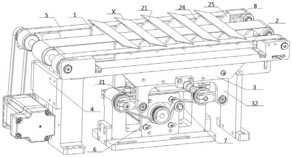
[0064] see figure 1 — Figure 7 , an online film turning machine, including a conveying device and a material turning device, the conveying device conveys a sheet X along the horizontal direction; the conveying device includes at least one conveyor belt 5, and the material turning device includes at least one sheet Stirrer 1;

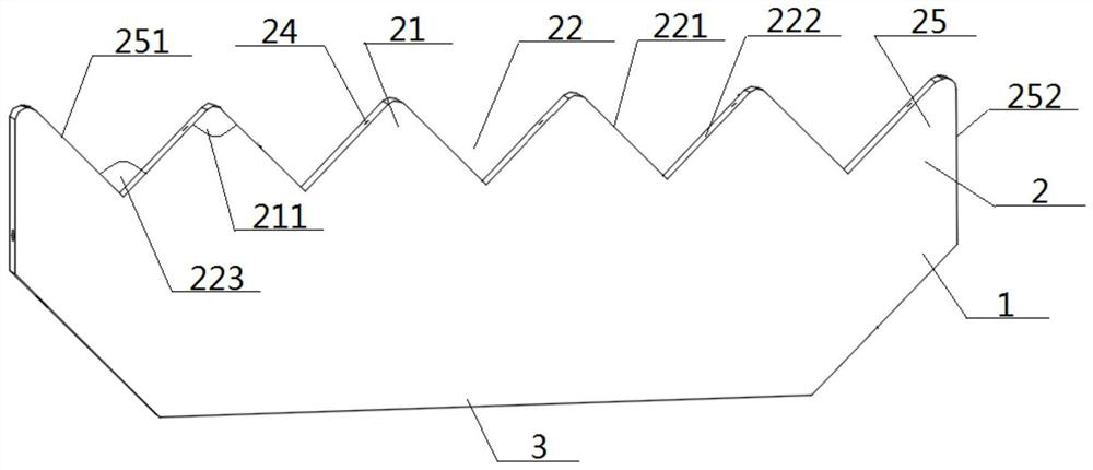
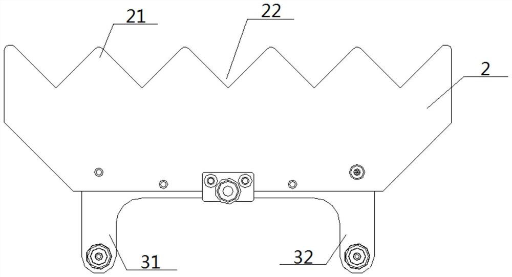
[0065] The top of the sheet material turning rack 1 is provided with a turning part 2, and the turning part 2 includes a plurality of turning teeth 21 connected in sequence, and a turning groove 22 is sandwiched between adjacent turning teeth 21, correspondingly A material turning tooth 21 is sandwiched between adjacent turning troughs 22; said turning trough 22 includes a No. 1 inclined plane 221 and a No. 2 inclined plane 222, and the tops of the No. 1 inclined plane 221 and the No. 2 inclined plane 222 extend upward toward opposite directions. The bottom ends of the No. 1 slope 221 and the No. 2 slope 222 intersect to form a groove angle 223;

[0...

Embodiment 2

[0070] Same as embodiment 1, this implementation also includes a driving device, the driving device is a driving device such as a cylinder, a cam mechanism, the driving end is connected to the bottom of the sheet material turning frame 1, and the sheet material turning frame 1 is driven to go up and down. sports.

Embodiment 3

[0072] The basic content is the same as that of implementation 1, the difference is that: the turning part 2 makes a circular motion, and during the process, the turning part 2 goes up so that the turning groove 21 is not lower than the conveyor belt 5, so that the sheet X is turned into the turning groove 22 and pasted On the No. 1 inclined plane 221 or the No. 2 inclined plane 222, the movement produces an acceleration away from the other inclined plane, so that the sheet X is turned over and attached to the other inclined plane, and the material turning tooth 21 is not higher than the conveyor belt 5 when moving downwards, so that after turning over The sheet X is placed on the conveyor belt 5, see for details Figure 6 .


PUM


Abstract

The invention discloses an online sheet turning machine. A conveying device in the online sheet turning machine comprises at least one conveying belt. A material turning device comprises at least onesheet turning frame. A material turning part is arranged at the top of each sheet turning frame. Each material turning part comprises a plurality of material turning teeth and material turning grooveswhich are sequentially connected at intervals, and each material turning groove comprises a first inclined face and a second inclined face. The top ends of the first inclined face and the second inclined face extend upwards in opposite directions, and the bottom ends of the first inclined face and the second inclined face intersect to form a groove included angle. The number of the sheets is at least two, the operation direction of the material turning part comprises vertical upward jacking and vertical downward moving, and the arrangement structures of the conveying belts and the sheet turning frames are that at least one sheet turning frame is arranged in the adjacent conveying belts, or at least one conveying belt is arranged in the adjacent sheet turning frames. According to the online sheet turning machine, the sheet turning efficiency is high, a sheet tidying function is achieved, online sheet turning can be achieved, the structure is simple, and the cost is low.

Description

technical field [0001] The invention relates to a film turning device, which belongs to the technical field of transmission, in particular to an online film turning machine. Background technique [0002] In the production process of solar cells, it is sometimes necessary to turn the cells 180 degrees. For example, in the shingling process, it is necessary to cut the cells into multiple pieces, then turn the multiple pieces over, and then perform the shingling process. [0003] The film turning device in the prior art mostly adopts the method of setting a turning frame between two transmission modules for turning over, such as setting a turning wheel between the two transmission modules, and the turning wheel is evenly arranged around the center Several wire slots, the wire slots are used to insert silicon wafers, one end of the turning wheel is connected to the driving motor, and the turning wheel is connected to the central axis of the driving motor and the center of the an...

Claims


Application Information

Patent Timeline
IPC IPC(8): B65G15/12B65G47/252B65G47/22B65G47/28H01L31/18
CPCB65G15/12B65G47/252B65G47/22B65G47/28H01L31/18B65G2201/022Y02P70/50
Inventor 徐贵阳
Owner WUHAN DR LASER TECH CORP LTD
Learn More