
Non-contact laser chip removal robot

A non-contact, laser cutting technology, used in laser welding equipment, welding equipment, metal processing equipment, etc., can solve the problems of scratches on the hole wall and valve cavity, low removal efficiency, and high labor intensity for operators. The effect of reducing labor intensity, not easy to damage, and high removal efficiency

Inactive Publication Date: 2021-02-02
JINGMEN YIMEI IND DESIGN CO LTD
View PDF0 Cites 0 Cited by
  • Summary
  • Abstract
  • Description
  • Claims
  • Application Information

AI Technical Summary

Problems solved by technology

[0002] After the valve is drilled, debris often sticks to the intersection of the orifice, and these debris need to be removed before spraying the valve. However, due to the limitations of the valve structure, manual work is still the main method at present, resulting in The labor intensity of the operator is high, the removal efficiency is low, and manual operation is easy to cause scratches on the hole wall and the inner cavity of the valve

Method used


Image

  • Non-contact laser chip removal robot
  • Non-contact laser chip removal robot
  • Non-contact laser chip removal robot

Examples


Embodiment Construction

[0024] The present invention will be described in further detail below in conjunction with the accompanying drawings and specific embodiments, and the implementation scope of the present invention is not limited thereto.

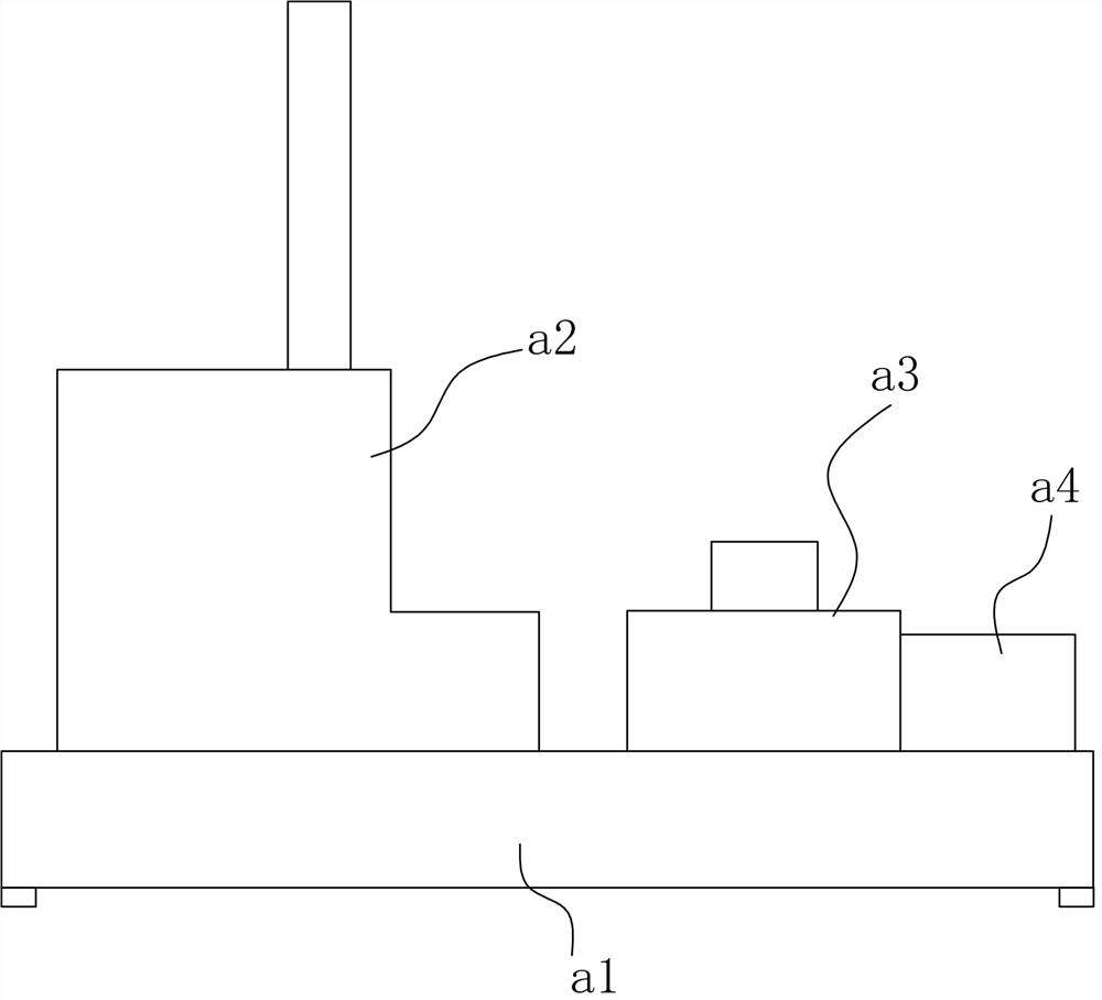
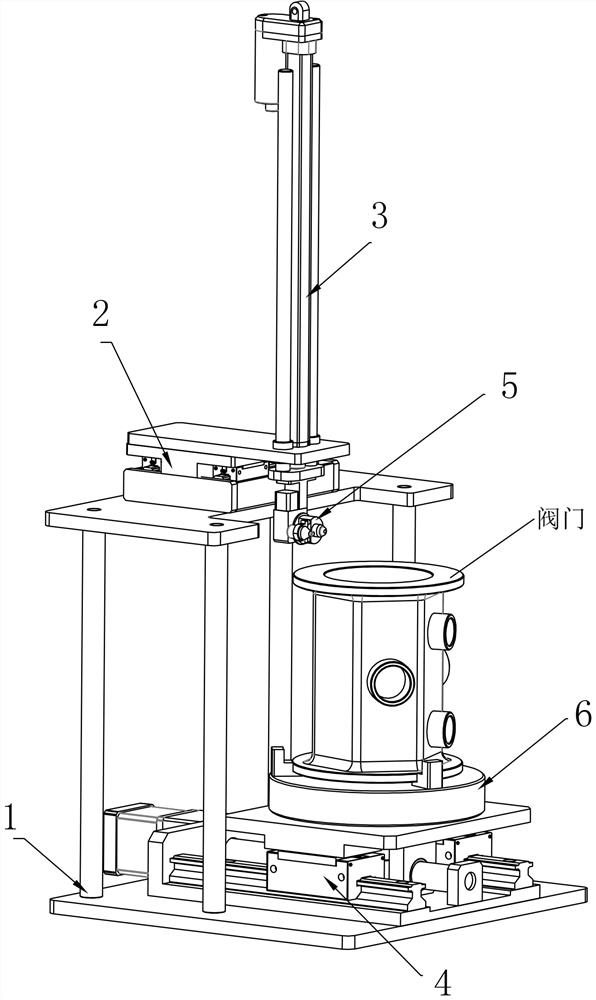
[0025] like Figure 1 to Figure 6 As shown, a non-contact laser chip removal robot described in this embodiment includes an organic table a1, a non-contact laser chip removal structure a2 provided on one end of the machine table a1, and a non-contact laser chip removal structure a2 provided on the other end of the machine table a1 The transfer table a4, and the material transfer robot a3 arranged on the machine table a1 and between the non-contact laser chip removal structure a2 and the transfer table a4.

[0026] In actual use, the transfer table a4 first moves the valves to be removed to the waiting area, and then the material transfer robot a3 transfers the valves in the waiting area on the transfer table a4 and places them on the non-contact laser chip r...


PUM


Abstract

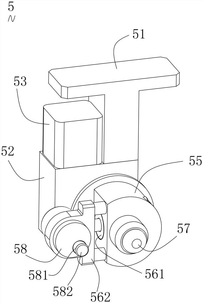
The invention discloses a non-contact laser chip removal robot. The robot comprises a machine table, a non-contact laser chip removal structure arranged at one end of the machine table, a conveying table arranged at the other end of the machine table, and a material moving mechanical arm arranged on the machine table and located between the non-contact laser chip removal structure and the conveying table; the non-contact laser chip removal structure comprises a rack, a first sliding table arranged at the top of the rack, a lifting mechanism arranged at the output end of the first sliding table, a second sliding table arranged at the bottom of the rack, a variable-diameter laser chip removal component arranged at the output end of the lifting mechanism and a rotary clamping mechanism arranged at the output end of the second sliding table; the rack is fixed to the machine table; and the movement direction of the first sliding table is perpendicular to the movement direction of the secondsliding table. According to the robot, mechanical operation is achieved, the removing efficiency is high, the labor intensity of operators is reduced, the production cost is reduced, contact with a valve is not required, and the valve is not prone to damage.

Description

technical field [0001] The invention relates to a non-contact laser chip removal robot. Background technique [0002] After the valve is drilled, debris often sticks to the intersection of the orifice, and these debris need to be removed before spraying the valve. However, due to the limitation of the valve structure, manual work is still the main method at present, resulting in The labor intensity of the operator is high, the cleaning efficiency is low, and the manual operation is easy to cause scratches to the hole wall and the inner cavity of the valve. Contents of the invention [0003] The object of the present invention is to overcome the above-mentioned shortcomings and provide a non-contact laser chip removal robot. [0004] To achieve the above object, the specific scheme of the present invention is as follows: [0005] A non-contact laser chip removal robot includes an organic table, a non-contact laser chip removal structure arranged on one end of the machine ...

Claims


Application Information

Patent Timeline
Patent Type & Authority Applications(China)
IPC IPC(8): B23K26/36B23K26/70
CPCB23K26/36B23K26/702
Inventor 秦群
Owner JINGMEN YIMEI IND DESIGN CO LTD
Learn More