
Plasma cleaning machine

A technology for a plasma cleaning machine and a cleaning chamber, applied in the field of ion cleaning, can solve the problems of poor cleaning effect, uneven distribution of gas diffusion, complex and redundant conductive lines, etc.

Pending Publication Date: 2021-02-02
KUNSHAN PLAUX ELECTRONICS TECH CO LTD
View PDF0 Cites 0 Cited by
  • Summary
  • Abstract
  • Description
  • Claims
  • Application Information

AI Technical Summary

Problems solved by technology

[0002] Plasma cleaning machines are mostly used in the semiconductor field. Plasma cleaning machines can clean lead frames, PCB boards, wafers, ceramics and other materials. The existing plasma cleaning machines have unreasonable structural design, small cleaning space, and low efficiency; plasma cleaning When the machine is working, it needs to ionize the gas to form plasma to clean the material. The existing plasma cleaning machine has complex and redundant internal conductive lines, occupies a volume, and is very inconvenient for daily use and maintenance, which affects production efficiency and high production costs; Some plasma cleaners have relatively concentrated gas flow direction, uneven gas diffusion distribution, poor gas ionization effect, and poor cleaning effect.

Method used


Image

  • Plasma cleaning machine
  • Plasma cleaning machine
  • Plasma cleaning machine

Examples


Embodiment Construction

[0033] The present invention will be further described below in conjunction with the accompanying drawings. The following examples are only used to illustrate the technical solution of the present invention more clearly, but not to limit the protection scope of the present invention.

[0034] In describing the present invention, it should be understood that the terms "center", "longitudinal", "transverse", "upper", "lower", "front", "rear", "left", "right", " The orientations or positional relationships indicated by "vertical", "horizontal", "top", "bottom", "inner" and "outer" are based on the orientations or positional relationships shown in the drawings, and are only for the convenience of describing the present invention and Simplified descriptions, rather than indicating or implying that the device or element referred to must have a particular orientation, be constructed and operate in a particular orientation, and thus should not be construed as limiting the invention. ...


PUM


Abstract

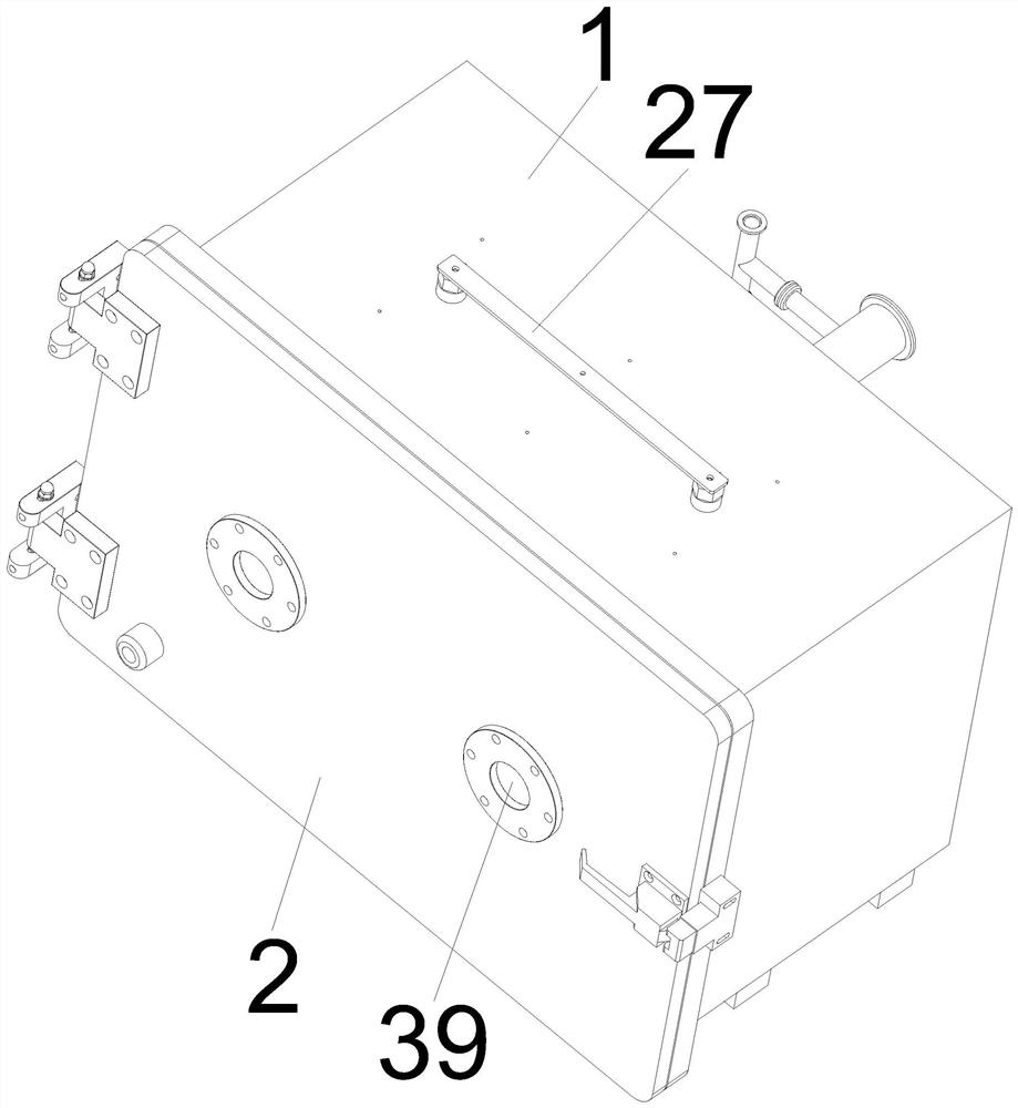
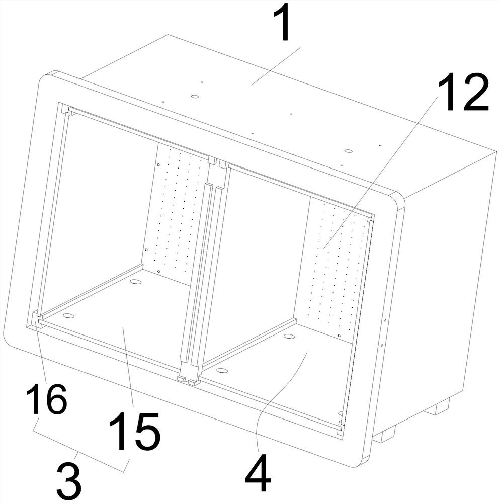
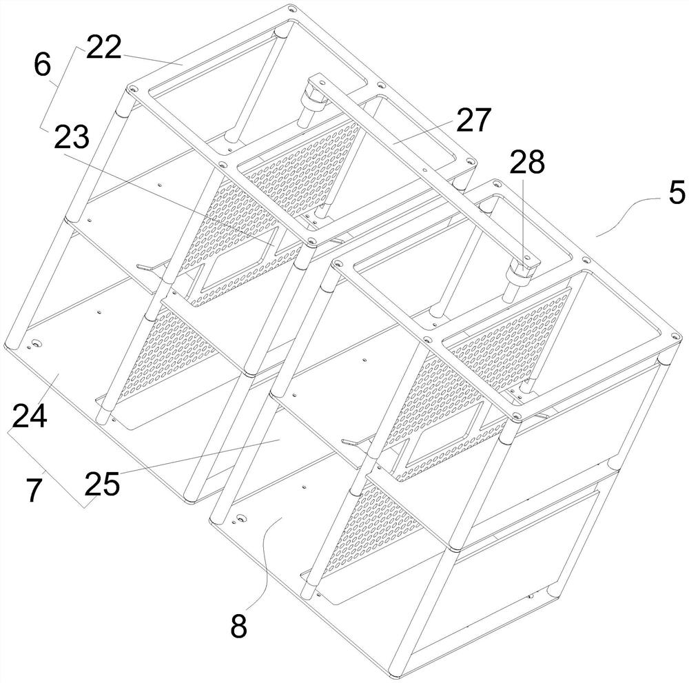
The invention relates to a plasma cleaning machine, and belongs to the technical field of plasma cleaning. The plasma cleaning machine comprises a box body and a box door, wherein the interior of thebox body is divided into a plurality of cleaning cavities by insulation isolation devices, a storage frame is arranged in each cleaning cavity, each storage frame is made of a conductive material andcomprises a positive electrode conductive half part and a negative electrode conductive half part, and the negative electrode conductive half parts are electrically connected with the box body; and the positive electrode conductive half parts are electrically connected with a positive electrode of a power supply outside the box body and do not make contact with the negative electrode half parts, the storage frames are divided into a plurality of storage cavities by the positive electrode conductive half parts and the negative electrode conductive half parts, the box body and the box door are provided with gas guide devices, and the gas guide devices can supply gas to and exhaust the gas from each storage cavity. The plasma cleaning machine is simple and reasonable in structure, high in space utilization rate, convenient to use and maintain, uniform in gas distribution and good in gas ionization and cleaning effect.

Description

technical field [0001] The invention relates to a plasma cleaning machine, belonging to the technical field of plasma cleaning. Background technique [0002] Plasma cleaning machines are mostly used in the semiconductor field. Plasma cleaning machines can clean lead frames, PCB boards, wafers, ceramics and other materials. The existing plasma cleaning machines have unreasonable structural design, small cleaning space, and low efficiency; plasma cleaning When the machine is working, it needs to ionize the gas to form plasma to clean the material. The existing plasma cleaning machine has complex and redundant internal conductive lines, occupies a volume, and is very inconvenient for daily use and maintenance, which affects production efficiency and high production costs; Some plasma cleaners have relatively concentrated gas flow direction, uneven gas diffusion distribution, poor gas ionization effect, and poor cleaning effect. Contents of the invention [0003] The object o...

Claims


Application Information

Patent Timeline
Patent Type & Authority Applications(China)
IPC IPC(8): B08B7/00B08B13/00
CPCB08B7/00B08B13/00
Inventor 郭峰王宇
Owner KUNSHAN PLAUX ELECTRONICS TECH CO LTD
Learn More