Proximal tibia bone cement pressurizing device

A compression device and bone cement technology, applied in the field of medical devices, can solve the problems of easy early loosening, less bone cement, and bone cement intrusion, etc., and achieve the effect of increasing life expectancy

Pending Publication Date: 2021-02-02
潘建康
View PDF0 Cites 0 Cited by
  • Summary
  • Abstract
  • Description
  • Claims
  • Application Information

AI Technical Summary

Problems solved by technology

[0003] At present, the technical features of tibial bone cement in knee arthroplasty are as follows: fully expose the osteotomy surface of the proximal tibia, pulse flush the tibial plateau, thoroughly remove the fat and debris on the surface, and place the prepared bone cement on the proximal tibial cut surface. On the bone surface, apply the bone cement evenly, and apply a little bone cement on the underside of the tibial tray and the keel, and then blow it into the proximal tibia. Since the osteotomy surface of the proximal tibia is an open oval plane, it cannot be well The bone cement is pressed into the cancellous bone at the proximal end of the tibia, so that the amount of bone cement entering the tibial plateau is relatively small, so that the fixation of the tibial prosthesis and tibial plateau can withstand less shear force, and it is easy to loose early after surgery

Method used


Image

  • Proximal tibia bone cement pressurizing device
  • Proximal tibia bone cement pressurizing device
  • Proximal tibia bone cement pressurizing device

Examples


Embodiment 1

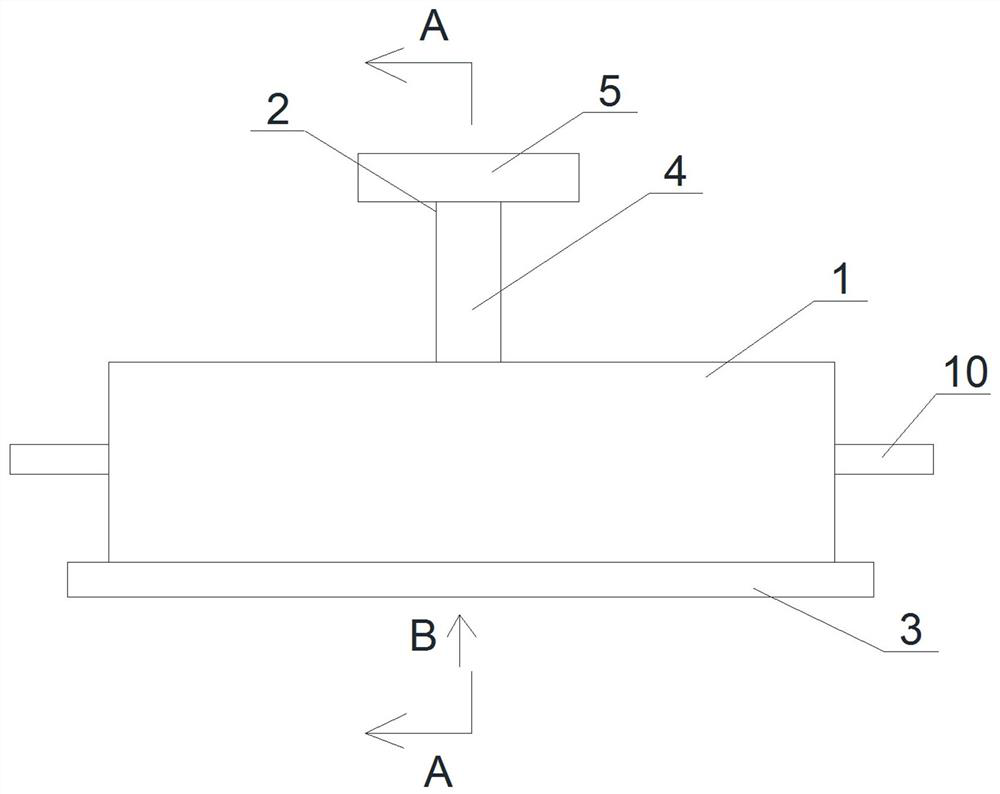
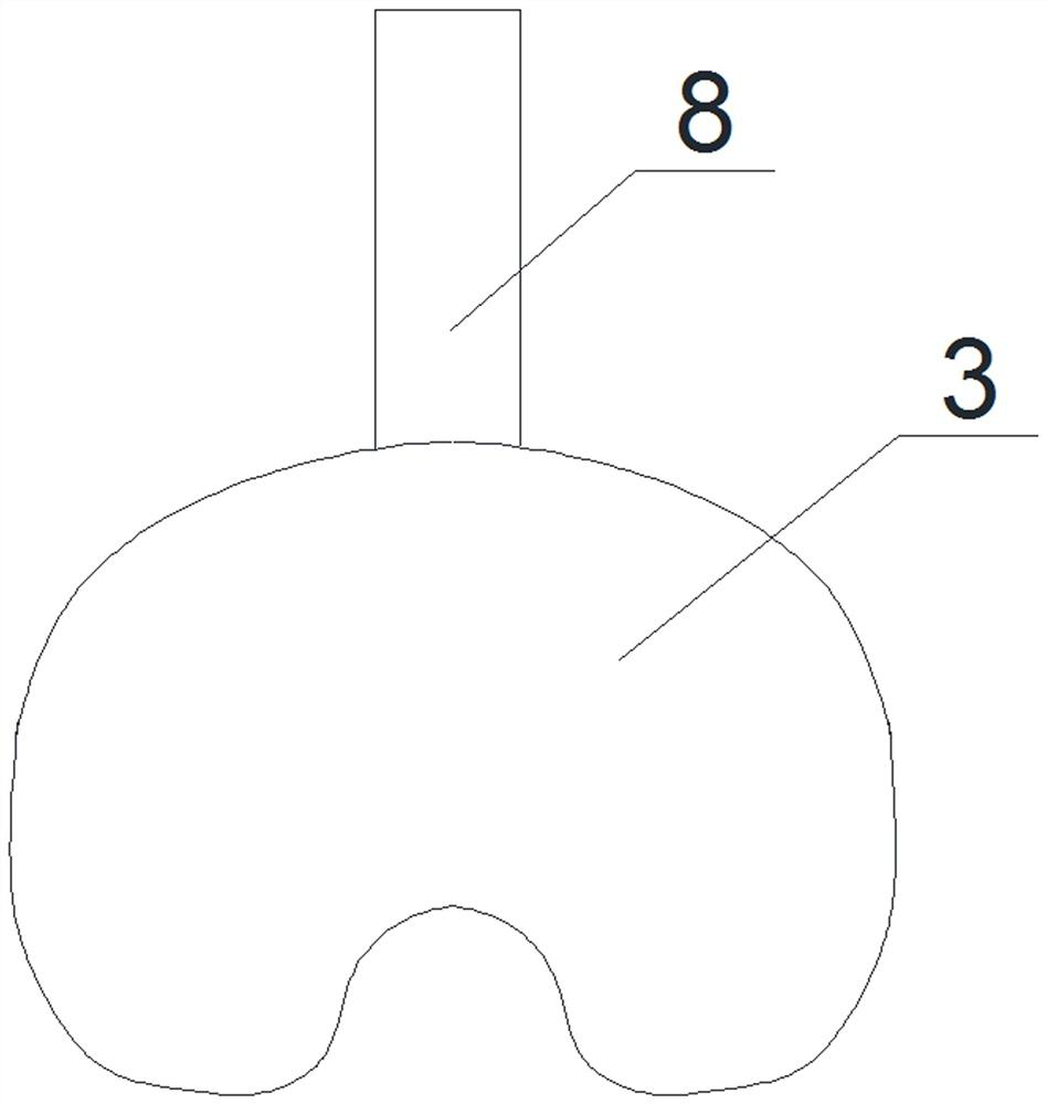
[0030] Such as Figure 1 to Figure 4 As shown, a proximal tibial bone cement pressurization device includes a cylinder body 1, a pressure plate 6 located in the cylinder body 1 and sealingly connected with the cylinder body 1 to move along the length direction of the cylinder body 1, and a pressure plate 6 The top of the cylinder is fixedly connected and the driving mechanism 2 that drives the pressure plate 6 to move in the vertical direction, the baffle 3 located under the cylinder 1 and used to block the bottom of the cylinder 1, the size of the baffle 3 is larger than that of the cylinder 1 Cross-sectional size, the bone cement is located in the cylinder 1 and on the lower surface of the compression plate 6, and the bone cement is pressed into the cancellous bone at the proximal end of the tibia by applying pressure to the compression plate 6. The cylinder 1 is vertically The height in the direction is 20 mm, the wall thickness is 2 mm, the thickness of the compression pla...

Embodiment 2

[0033] Such as Figure 1 to Figure 4As shown, a proximal tibial bone cement pressurization device includes a cylinder body 1, a pressure plate 6 located in the cylinder body 1 and sealingly connected with the cylinder body 1 to move along the length direction of the cylinder body 1, and a pressure plate 6 The top of the cylinder is fixedly connected and the driving mechanism 2 that drives the pressure plate 6 to move in the vertical direction, the baffle 3 located under the cylinder 1 and used to block the bottom of the cylinder 1, the size of the baffle 3 is larger than that of the cylinder 1 Cross-sectional size, the bone cement is located in the cylinder 1 and on the lower surface of the compression plate 6, and the bone cement is pressed into the tibial plateau by applying pressure to the compression plate 6, and the height of the cylinder 1 in the vertical direction is 30mm, the wall thickness is 3mm, the thickness of the compression plate 6 is 10mm, the barrel 1 is made ...

Embodiment 3

[0037] Such as Figure 9 As shown, the difference between this embodiment and Embodiment 1 is only that: the operating rod 4 is covered with a limiting plate 16, the limiting plate 16 is threadedly connected with the outer surface of the operating rod 4, and the cross-sectional area of ​​the limiting plate 16 is Greater than the cross-sectional area of ​​the cylinder body 1, the limit plate 16 is located on the horizontal plane, and the outer surface of the operating rod 4 is provided with threads and scale values, which is convenient for controlling the amount of bone cement in the cylinder body 1, and the limit plate 16 is in contact with the cylinder body. The top of the body 1 touches to prevent the operation rod 4 from continuing to move downward, thereby controlling the amount of bone cement in the cylinder body 1 entering the spongy bone at the proximal end of the tibia. threaded hole, turn the limit plate 16, the limit plate 16 moves relative to the length direction of...


PUM

PropertyMeasurementUnit
Heightaaaaaaaaaa
Wall thicknessaaaaaaaaaa
Thicknessaaaaaaaaaa

Abstract

The invention discloses a proximal tibia bone cement pressurizing device. The proximal tibia bone cement pressurizing device comprises a barrel, a pressurizing plate, a driving mechanism and a baffle,wherein the pressurizing plate is located in the barrel, is in sealed connection with the barrel and moves in the length direction of the barrel, the driving mechanism is fixedly connected with the top of the pressurizing plate and drives the pressurizing plate to move in the vertical direction, and the baffle is located below the barrel and used for blocking the bottom of the barrel. Bone cementis located in the barrel and located on the lower surface of the pressurizing plate, and the bone cement is pressed into proximal tibia cancellous bone by applying pressure to the pressurizing plate.By arrangement of the pressurizing plate and the driving mechanism, the bone cement can be conveniently pressed into the proximal tibia cancellous bone, the amount of the bone cement entering the proximal tibia cancellous bone is large, the bone cement entering the proximal tibia cancellous bone is deep, a proximal tibia and a tibia prosthesis are well fixed, larger shearing force can be borne, the probability of sterile loosening of the prosthesis caused by bone cement technical defects after total knee replacement is not likely to occur, and therefore, the service life of the knee joint prosthesis is prolonged.

Description

technical field [0001] The invention relates to the technical field of medical instruments, in particular to a bone cement pressurizing device at the proximal end of the tibia. Background technique [0002] After total knee arthroplasty, aseptic loosening of the prosthesis mostly occurs on the tibial side, part of which is due to poor bone cement filling on the tibial side. Poor bone cement technology leads to insufficient cement thickness between the prosthesis and the bone end, especially on the tibial side, resulting in insufficient shear force that the tibial side prosthesis can withstand, and the shear force generated by multiple flexion and extension activities of the knee joint Therefore, the thickness of the bone cement on the tibial side is very important. In total knee arthroplasty, the tibial plateau is an open oval plane, which is completely different from the proximal femur in hip arthroplasty. In hip replacement, the proximal femoral medullary cavity is a dis...

Claims


Application Information

Patent Timeline
IPC IPC(8): A61B17/88
CPCA61B17/8805
Inventor 潘建康
Owner 潘建康
Why Eureka
Try Eureka