
Full-automatic fresh tea leaf ventilating storage device

A fully automatic, tea-leafing technology, applied in tea processing before extraction, etc., can solve problems such as difficulty in adequate ventilation and drying, and achieve the effect of drying and heat dissipation

Inactive Publication Date: 2021-02-02
德清之家纺织有限公司
View PDF0 Cites 1 Cited by
  • Summary
  • Abstract
  • Description
  • Claims
  • Application Information

AI Technical Summary

Problems solved by technology

[0005] The purpose of the present invention is to solve the problem that most traditional tea leaves are difficult to be fully ventilated and dried in the green storage process, and to provide a fully automatic tea green storage device that can fully ventilate and dry the tea leaves

Method used


Image

  • Full-automatic fresh tea leaf ventilating storage device
  • Full-automatic fresh tea leaf ventilating storage device

Examples


Embodiment 1

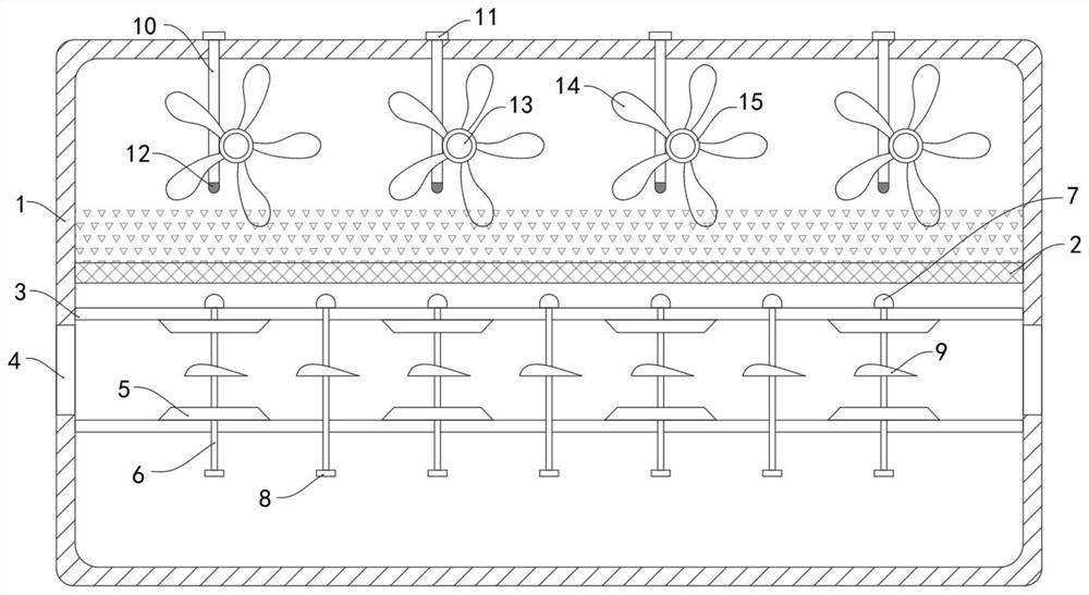
[0021]Such asfigure 1 As shown, a fully automatic green tea storage device includes a fixed frame 1, in which a horizontally arranged elastic net 2 is fixedly connected to the fixed frame 1, and the tea leaves are laid flat on the elastic net 2 during the working process. The density of the tea water vapor If it is larger than air, it will move below the elastic net 2, and the air flow will flow from the lower end of the elastic net 2, which can fully take away the moisture of the tea leaves and play a better drying effect.

[0022]There are two fixed plates 3 arranged horizontally under the elastic net 2, and the side walls of the fixed frame 1 between the two fixed plates 3 are provided with ventilation holes 4, and the two fixed plates 3 are fixed on the opposite side walls. A plurality of evenly arranged fixing blocks 5 are connected, and the plurality of fixing blocks 5 on the two fixing plates 3 are arranged one by one, a narrow air passage is formed between the two fixing blocks...

Embodiment 2

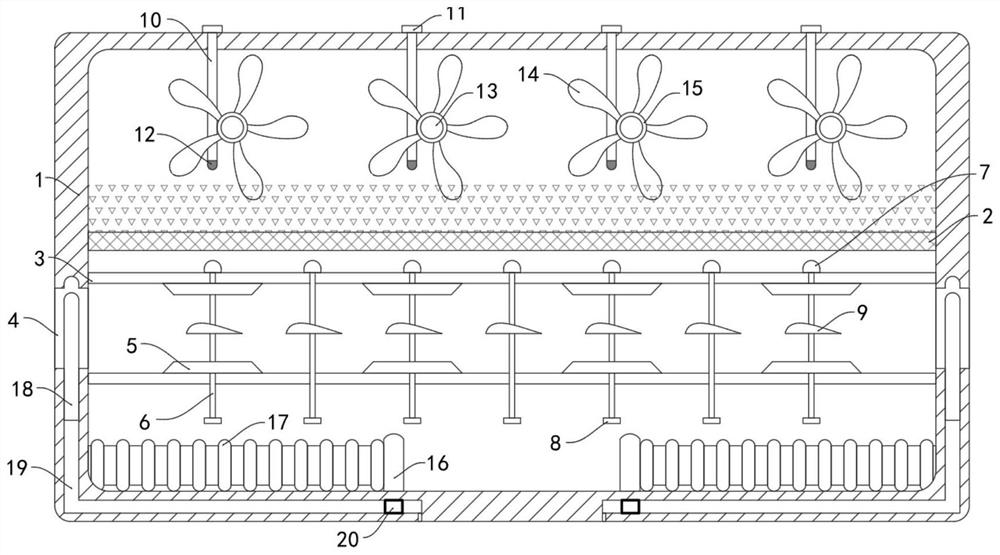
[0033]Such asfigure 2As shown, the difference between this embodiment and embodiment 1 is that: the inner bottom surface of the fixed frame 1 is slidably connected with two magnetic sliding plates 16, and the two magnetic sliding plates 16 and the side walls of the fixed frame 1 are fixedly connected with internal The elastic bellows 17 containing the evaporating liquid, the two vent holes 4 are slidably connected with a closing plate 18, the side wall of the fixing groove 1 is provided with an air passage 19 matching the closing plate 18, and the other end of the air passage 19 slides A magnetic sliding block 20 that attracts opposite poles of the magnetic sliding plate 16 is connected.

[0034]In this embodiment, when the temperature in the fixed frame 1 is too high to the boiling point of the evaporating liquid, the evaporating liquid will vaporize in the elastic bellows 17. The elastic bellows 17 pushes the magnetic sliding plate 16 to move, and the magnetic sliding plate 16 moves ...


PUM


Abstract

The invention belongs to the field of tea processing and treatment, and particularly relates to a full-automatic fresh tea leaf ventilating storage device. The full-automatic fresh tea leaf ventilating storage device comprises a fixing frame; a horizontally-arranged elastic net is fixedly connected into the fixing frame; two horizontally-arranged fixing plates are arranged below the elastic net; vent holes are formed in the side wall of the fixing frame located between the two fixing plates; a plurality of evenly-distributed fixing blocks are fixedly connected to the opposite side walls of thetwo fixing plates; the fixing blocks on the two fixing plates are arranged in a one-to-one correspondence mode; and a vertically-arranged lifting rod is arranged between every two corresponding fixing blocks. By arranging stirring fans, in the ascending and descending process of the lifting rods, each rack can move up and down under the repulsion effect of a magnetic block at the top of each lifting rod and the gravity effect of the rack, the rack moves up and down to drive the corresponding stirring fan to rotate through a corresponding gear on a rotating shaft, and each rotating stirring fan stirs tea leaves on the elastic net; and ventilation and heat dissipation of the tea leaves are further facilitated.

Description

Technical field[0001]The invention belongs to the field of tea processing and processing, and in particular relates to a fully automatic tea green storage device.Background technique[0002]There are many types of tea products sold on the market. According to the classification and processing of commercial teas, there are seven types of tea sold on the market in my country: black tea, green tea, scented tea, oolong tea, pressed tea, Pu'er tea and yellow tea. All of these tea leaves are processed from the fresh leaves, buds and twigs of the tea plant. Different processing methods result in different types of processed tea.[0003]In the tea processing process, the freshly picked tea leaves need to be placed in a constant temperature and ventilated place for storage. Most of the traditional processing methods are to spread the tea leaves flat or stack them in a warehouse with flowing air, but in this process, the bottom layer The long-term backlog of tea leaves is not conducive to ventila...

Claims


Application Information

Patent Timeline
IPC IPC(8): A23F3/06
CPCA23F3/06
Inventor 徐辉
Owner 德清之家纺织有限公司
Learn More